
Badar (BAZ)
-
Posts
517 -
Joined
-
Last visited
-
Days Won
278
Reputation Activity
-

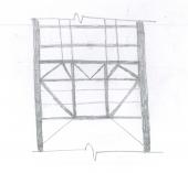
 Badar (BAZ) got a reaction from Muhammad SAqib shah in Roof truss deign , member length?
Look for any unconnected member.
-

 Badar (BAZ) got a reaction from UmarMakhzumi in Seismic and Non Seismic Detailing in CSI Detailer
Waslaam,
Lap splices are prohibited within the region expected to develop a flexural hinge ( the region is approximately: 2 x member depth from the face of column for Bernoulli-Euler beams) to improve the post-yield deformation capacity in SMRF. This provision is there in the first code that I read (ACI 318-02); it still exists, as it should.
-
 Badar (BAZ) got a reaction from Howard Roark in Seismic and Non Seismic Detailing in CSI Detailer
Waslaam,
Lap splices are prohibited within the region expected to develop a flexural hinge ( the region is approximately: 2 x member depth from the face of column for Bernoulli-Euler beams) to improve the post-yield deformation capacity in SMRF. This provision is there in the first code that I read (ACI 318-02); it still exists, as it should.
-
 Badar (BAZ) got a reaction from Waqar Saleem in Seismic and Non Seismic Detailing in CSI Detailer
Waslaam,
Lap splices are prohibited within the region expected to develop a flexural hinge ( the region is approximately: 2 x member depth from the face of column for Bernoulli-Euler beams) to improve the post-yield deformation capacity in SMRF. This provision is there in the first code that I read (ACI 318-02); it still exists, as it should.
-
Badar (BAZ) got a reaction from Waqar Saleem in Seismic Design
The author reminds me of Taher Shah (self-proclaimed musician).
-
 Badar (BAZ) got a reaction from Sameer Khan in Property Modifiers
In ETABS, you can modify geometric properties of section either from within "Frame section property data" window, or by going trough this route: Assign > frame > property modifier.
You have used the first option. When you do that, the information will not appear in "beam information" window. But you still got your property modifiers, which you can see when you go to the "Frame section property data" window.
-
 Badar (BAZ) got a reaction from G_Farooq in Modelling Issues/consideration in ETABS
I want to comment on some modelling issues in ETABS. Though some of these things are discussed elsewhere in the forum, I hope to extract some more useful conclusions.
First thing is related to modelling the bending stiffness of flexural members, for strength level loads, that is representative of their condition near failure.
The ACI code specifies the modifier of 0.35 on gross moment of inertia to represent its condition at yielding.
Some people say that the factor should be multiplied by 2 to represent the stiffness of T-beam. This approach would be justified if you are not taking into the account the out of plan bending stiffness of slab.
But, ETABS does include the out of plane bending stiffness if you have modelled the slab by using shell elements. So, a factor of 0.7 would overestimate the stiffness of your structure in this case, and will lead to under-design.
If one has used the modifier of 0.35 in ETABS for beams in beam-slab floor system, then what value should be adopted for slab? It should not be 0.25, as this value has been specified for flat plates and flat sab floor system.
If one is using some value of modifier for out of plane bending stiffness on shells, then the share of the bending moment in beams will be reduced accordingly. This approach is correct if one will be providing the reinforcement in column strips of slab. But, if you are providing reinforcement in slab in the direction perpendicular to supports only, i.e. beams, as is the general practice in Pakistan, then you are under-estimating the flexural demand in beams.
Now, there is also a question of factors to be used while deciding the amount of reinforcement required in beams, columns and shear walls.
If you are using factors 0.35 for beams and shear walls, and 0.7 for columns, then you are finding out the demand in members at the point of yielding, and this conforms to the code. But, this also means that the structure might experience unacceptable cracks widths. So, if you are using 0.35 for calculating the demand at strength-level forces, then you should also perform crack-control-check at service-level loads by using the factor of 1.
If you are calculating the strength-level demand with a modifier of 1 for all structural members, after you have decided the location and the number of shear walls with modifier of 0.35, then you are overestimating seismic forces, as you are underestimating the time-period. But, the structural performance will improve.
-
Badar (BAZ) got a reaction from G_Farooq in Beam Column Joint
*SEFP Consistent Design*
*Pile Design*
*Doc No: 10-00-CD-0007*
*Date: April 16, 2018*
1.1. FUNCTION OF JOINT
Beam-column joint must transfer the forces, such as moment, shear and torsion, transferred by the beam to the column so that the structure can maintain its integrity to carry loads for which it is designed.
Another function of the beam-column joint is to help the structure to dissipate seismic forces so that it can behave in a ductile manner.
1.2.WHY DO WE CARE
During an extreme seismic event, the code-based structure is expected to maintain its load-carrying capacity for gravity loads even after the structure deforms into inelastic range so that it does not pose any life safety hazard. Hence, the joint can go through significant degradation of strength and stiffness, and if it fails in shear, or anchorage, the life-safety objective of code cannot be achieved.
1.3.CONSEQUENCES OF FAILURE
1.4.THINGS TO CONSIDER FOR BEAM COLUMN JOINT
Longitudinal bars of beams, or slab, must be able to develop their yield stress, so that the beam/slab can transfer moment to joint. It means that longitudinal bars must have adequate development length for hooked bars. This implies that the size of the column must be such that bars can develop their tensile forces. If bars can transfer moment, they can also transfer shear as far as monolithic construction is concerned. The shear strength of the joint must enable the transfer of moment and shear through it. The joint should be Constructible: Congestion of reinforcement is the main concern.
1.5.DESIGN SHEAR FOR BEAM COLUMN JOINT
The design shear for beam-column joint depends upon the relative strength of beam and column at the joint.
For the joints part of the special moment resisting frame, the shear force will be the one that corresponds to the development of hinge in the beam because the frame is required to satisfy strong column-weak beam criteria. If it is a knee joint, then joint area must resist the shear equal to the development of tensile force in the beam. The tensile force will be equal to the product of the area of tension steel, yield strength and the factor that represents the overstrength of steel rebar. If it is not a knee-beam-column joint then, the design shear of the joint will be algebraic sum of tensile force in the beam and the column shear. The column shear is the one that is required to keep the joint in equilibrium, i.e the shear corresponding to the development of the probable moment capacity of beams at the joint.
For the joints not part of the special moment resisting frames, one needs to investigate whether the beam or column will yield first. For knee joint, if the column is weaker then the beam, the tensile force cannot exceed the moment corresponding to the development of hinge in column
1.6.THE JOINT: Definition and classification
Portion of column within deepest beam that frames in to the column (ACI 352-02).
ACI 352-02 categorizes joints based on the displacement-demand imposed by connected members.
· TYPE 1 (Section 2.1.1 ACI 352-02)
These joints possess limited ductility, and hence the connected members are designed for limited ductility. They are used in situations where ductility of structure is not a concern.
· TYPE 2 (Section 2.1.2 ACI 352-02)
These joints connect members which designed to have sustained strength under large deformations.
Joints are also classified based on their location in framing system
1.7.THE JOINT: Design forces
The joint is designed for the shear that results from attainment of the flexural strengths of members connected at the joint for type 2 joints. For type 1 joints, same principle is employed, unless the both members are overdesigned and the engineer does not expect both members, i.e. beam and column, to yield under design forces.
1.7.1. FLEXURAL STREGNTHS: TYPE 2
No strength reduction factor is used for computation of flexural strength. Steel stress is multiplied by factor of 1.25 for computation of flexural strength (3.3.4 ACI 352-02). For type 2 joints, the flexural strength of beams needs to be calculated only, as we do not expect the hinge-formation in columns; we will proportion the beam-column assembly of this joint as per strong-column-weak-beam approach.
The slab reinforcement within the flange of beam must also be considered for computation of flexural strength of beam if the slab is integrally cast with beam and if the longitudinal reinforcement of slab is anchored (3.3.2 ACI 352-02).
For interior connections, and for exterior and corner connections with transverse beams, the portion of slab to be considered as flange should be as per guidelines of section 6.3.2 of ACI 318-14. The effective flange width should not be taken less than 2 times the width of beam.
For exterior and corner connections, without transverse beams, the effective flange width should be as per figures below (section 3.3.2 of ACI 352-02). The effective flange width for this case need not be taken more than 1/12th of the span of the beam.
1.7.2. FLEXURAL STREGNTHS: TYPE 1
For type 1 connection, similar procedure as discussed above should be used, if beams are expected to yield before columns. The stress multiplier factor for this type of connection can be taken as 1.
The beam reinforcement, if any, as per section 24.3.4 of 318-14, with-in the effective flange width, must be included in determination of flexural strength in addition to the web reinforcement.
If columns are expected to yield before beams, the nominal flexural capacity at beam-column joint should be calculated with due consideration given to the axial load on column. The beam moment in that case would be the one required to maintain equilibrium of the connection.
If neither the beam, nor column, is expected to yield at factored loads, then the design shear of joint would be based on factored forces, moments and shear, at beam-column interface.
-
Badar (BAZ) got a reaction from UmarMakhzumi in Beam taking action of Column
If there is no error in the model, then the planted column is not the major source of design forces for the cantilever. Check which load case is responsible for the transfer of sagging moment at the end of cantilever beam.
-
Badar (BAZ) got a reaction from UmarMakhzumi in Beam taking action of Column
Let me break down the BM diagrams for you.
The first case: High point load accompanied by a negligible bending moment transferred to the edge of the cantilever beam from the planted column. If we neglect the contribution of bending moment, we will get the following distribution of bending moment in each member.
If the planted column transfers huge bending moment ( and negligible point load) at the edge of the cantilever beam, following distribution will result
You are saying the you have assigned the hinge at the lower end of column, the end where it connects to the cantilever beam. If that's the case, you should get the BMD shown in the first figure.
-
 Badar (BAZ) got a reaction from Muhammad Hashmi in Beam taking action of Column
Let me break down the BM diagrams for you.
The first case: High point load accompanied by a negligible bending moment transferred to the edge of the cantilever beam from the planted column. If we neglect the contribution of bending moment, we will get the following distribution of bending moment in each member.
If the planted column transfers huge bending moment ( and negligible point load) at the edge of the cantilever beam, following distribution will result
You are saying the you have assigned the hinge at the lower end of column, the end where it connects to the cantilever beam. If that's the case, you should get the BMD shown in the first figure.
-
Badar (BAZ) got a reaction from Muhammad Hashmi in Beam taking action of Column
If there is no error in the model, then the planted column is not the major source of design forces for the cantilever. Check which load case is responsible for the transfer of sagging moment at the end of cantilever beam.
-
Badar (BAZ) got a reaction from UmarMakhzumi in Seismic factors (kv/kh or cv/ch) values
It is incorrect. You cannot get the seismic information of Pakistan from UBC 97.
It has been discussed somewhere else in the forum. The difference between new set of codes and UBC97, and earlier codes, is in the definition of design grounds motion parameters and design earthquake.
In Pakistani code, seismic forces of structure are still based on expected ground accelerations at site; they are expressed in terms of Ca & Cv (same as in UBC 97). Since 2000, codes no longer use them, instead they have developed zoning maps in term of design spectral accelerations at short period, Sds, and 1 second, S1 (it is argued that they represent the seismic input energy better than Ca and Cv). If you want to use ASCE, you need "Sds" and "S1" for your site; these values have been reported by several researchers (take a look at the publications listed below) for different regions of Pakistan. You will also find them, hopefully, in new code of Pakistan.
Probabilistic Seismic Hazard Analysis Based Zoning Map of Pakistan, Journal of Earthquake Engineering
Updated earthquake catalogue for seismic hazard analysis in Pakistan, J Seismology (2018) 22:841–86
-
Badar (BAZ) got a reaction from UmarMakhzumi in Etabs Mass Displacement for Accidental Torsion
Measure the eccentricity in grid system that has members providing the major stiffness and strength. If both coordinate system has such member, you can consider displacing the mass in both coordinate systems independently.
-
 Badar (BAZ) reacted to Nustian371 in Water tank leakage
You got quiet a few answers above, But i think the fundamental question is what is your tank design is it a steel liner tank with a additional liner layer inside for water proofing or is a pocket base, which i see in this case as the steel wall is embedded in the concrete. There are water seals around the tank wall in the pocket see examples of each below,
that is the liner one
You got that one. There is a waterseal as mentioned above if this seal is not isntalled carefully and if it gets broken or damaged somehow during site pore, the leak at the base can occur.
Normally the concrete slab for such tanks have a very high requirement of crack control so i doubt that if thats not considered in design.
I would recommend first check the design of the wall pocket (if the leak is there) and confirm with the site notes if the seal is provided. The remedial measures can only be suggested once the cause is known. There are several options which can be adopted.
-

-
Badar (BAZ) got a reaction from Ayesha in Etabs Mass Displacement for Accidental Torsion
Measure the eccentricity in grid system that has members providing the major stiffness and strength. If both coordinate system has such member, you can consider displacing the mass in both coordinate systems independently.
-
 Badar (BAZ) got a reaction from Suarez in Diaphragm Flexibility
Span of the diaphragm is the distance between vertical lateral load resisting elements. Yes, the same diaphragm can behave different in different directions.
Also read and understand following statement from the article:
The statement implies that when your are using shear walls in the building, the span of the diaphragm could be the distance (perpendicular to the lateral force) between shear walls, depending upon the relative stiffness of moment resisting frames and shear walls.
If the building has no shear walls, then the span is the distance (perpendicular to the lateral force) between column lines, or two consecutive frames.
-
Badar (BAZ) got a reaction from Suarez in Diaphragm Flexibility
*SEFP Consistent Design*
*Diaphragm Flexibility*
*Doc No: 10-00-CD-0004*
*Date: August 07, 2014*
I am writing this article about a very important, but mostly neglected topic of flexibility of diaphragm. I used to assume that all reinforced concrete slabs can be treated as rigid diaphragms. But as it turns out, only the slab with span-to-depth (depth is length of slab in direction of lateral loads) ratio of less than 3 and without horizontal irregularity can be treated as rigid diaphragm. The more important thing is that the span-to-depth ratio and horizontal irregularity is not the only criteria and one other factor also needs to be kept in mind before assigning rigid diaphragm to concrete slabs in numerical model of building.
Another important concept that I learned, and it was a moment of epiphany for me, is about TRANSFER diaphragms. I had posted a topic “Amplification Of Forces In Etabs” earlier in this forum but we were not able to reach at a satisfactory conclusion. Now, I have the answer to that query: Back Stay effect. Another article is required to explain it , and this concept is not discussed in this article. This article is about flexibility of diaphragm.
Diaphragms are horizontal members of the lateral-force resisting system of building structures. Their function is to distribute inertial forces, generated at its own level, as well as other levels, to vertical members of lateral-force resisting system.
One kind of diaphragm only distributes inertial forces generated at its own level. This kind of behaviour is observed in buildings where there is a continuity of vertical members of lateral-force resisting system: building should not have a setback or podium at lower levels, or below grade levels. The other kind of diaphragm, known as “Transfer diaphragm”, not only distributes inertial forces generated at its own level, but also re-distributes forces coming from upper levels. This type of behaviour is typical of a building having setback or podium at lower levels, or below grade levels. Transfer slabs can attract huge forces due to a behaviour dubbed as BACKSTAY EFFECT.
Now, coming to the issue of flexibility of diaphragm. According to ASCE 7-10,
In addition to considering aspect ratio and horizontal irregularity as a basis for assuming concrete slab as a rigid diaphragm, the relative stiffness of adjoining vertical lateral load resisting system. Buildings with shear walls at ends and flexible frames in between are the ones where the assumption of rigid diaphragm leads to underestimation of drifts and erroneous distribution of base shear in vertical as well as horizontal direction (1)(2)(3); shear forces in middle frames can be reduced to 23% if rigid diaphragm is assigned in the model (1) for buildings with this type of structural configuration.
M. Moeini et al. (2008) (3) conducted a parametric study using numerical analysis and proposed formulae that predicts the error associated with assuming concrete slab as rigid diaphragm. They also concluded that for buildings, without shear walls, rigid diaphragm assumption is suitable for irregular buildings as well. But, for long and narrow buildings with shear walls at ends, the assumption of rigid diaphragm is not suitable.
The objective of writing this article was to warn engineers about the tendency of blindly assigning rigid diaphragm to concrete slab in any type of building configuration. The result could be underestimation of forces as well as drifts.
Nakashima, M., Huang, T., Lu, L-W. “ Effect of Diaphragm Flexibility on Seismic Response of Building Structures”, In proceedings of 8th world conference on earthquake engineering. San Luis Obispo, MSc Thesis , “ An Investigation of influence of diaphragm flexibility on building design through comparison of forced vibration testing and computational analysis”, 2010. M. Moeini, B. Rafzey, W.P. Howsen, “Investigation into the floor diaphragm flexibility in rectangular reinforced concrete buildings and error formulae”, In proceedings of 14th world conference on earthquake engineering.
The article is not finalized and would be completed in coming weeks.
-
-
Badar (BAZ) got a reaction from Muhammad Hashmi in Etabs Mass Displacement for Accidental Torsion
Measure the eccentricity in grid system that has members providing the major stiffness and strength. If both coordinate system has such member, you can consider displacing the mass in both coordinate systems independently.
-
-
 Badar (BAZ) got a reaction from Shahzad Khan in ETABS - Identify which walls have cracks
Yes, its enough to figure out if the tensile stresses in RC walls are exceeding the capacity of concrete to take tension, which means there will be cracks if it does that.
-
Badar (BAZ) reacted to Waqar Saleem in Responsibility of Structural Designs!!!
Copied from Eng-tips
https://www.eng-tips.com/viewthread.cfm?qid=485307
MEXICO CITY, July 14 (Reuters) - A Mexican court has sentenced a man to 208 years in prison for the criminal homicides of 26 people, most of them children, who died when a school collapsed during a powerful earthquake that struck Mexico City in 2017, authorities said on Wednesday.
The Mexico City attorney general's office said it had shown that the man described as a works director had guaranteed the structural safety of the school in Tlalpan, a southern district of the capital, without carrying out the required testing and despite irregularities in the building's construction.
-
Badar (BAZ) got a reaction from UmarMakhzumi in ETABS - Identify which walls have cracks
Yes, its enough to figure out if the tensile stresses in RC walls are exceeding the capacity of concrete to take tension, which means there will be cracks if it does that.