
Badar (BAZ)
-
Posts
517 -
Joined
-
Last visited
-
Days Won
278
Reputation Activity
-

 Badar (BAZ) got a reaction from Shahzad Khan in ETABS - Identify which walls have cracks
Yes, its enough to figure out if the tensile stresses in RC walls are exceeding the capacity of concrete to take tension, which means there will be cracks if it does that.
-

 Badar (BAZ) got a reaction from UmarMakhzumi in Beams
There is no beam-slab connection approach in ETABS. It can include the stiffness of flange automatically if you have defined a shell element for representing your slab, but it will calculate the required flexural rebars based on the cross-section defined for the line (beam) element.
Define a T-section if you want include the effect of flange for positive-moment capacity. In that case, you need to model the slab carefully; area element with shell property can result in over-estimation of stiffness if stiffness modifiers are not applied appropriately.
-
 Badar (BAZ) got a reaction from Moses Fukiza in Beams
There is no beam-slab connection approach in ETABS. It can include the stiffness of flange automatically if you have defined a shell element for representing your slab, but it will calculate the required flexural rebars based on the cross-section defined for the line (beam) element.
Define a T-section if you want include the effect of flange for positive-moment capacity. In that case, you need to model the slab carefully; area element with shell property can result in over-estimation of stiffness if stiffness modifiers are not applied appropriately.
-
 Badar (BAZ) got a reaction from Muhammad Hashmi in Dual System Modeled as Sway/Non-Sway?
Yes, they will be ignored.
But why do you want to select the non sway option? Your design moments will not be effected much by the moment magnification factors and P-delta analysis if l/r ratio of columns is small, and if lateral drifts are also with in the limits.
If you are enabling the P-delta analysis option, program will magnify your column moments anyway based on the results of P-delta iterations even if non-sway option has been selected (sway part of moment magnification equation of ACI 318 is still there because of lateral loads).
One should not rely on the seismic checks performed by ETABs. Unless you have specified the actual reinforcement ( the ones in structural drawings) to the program, these results are useless.
-
Badar (BAZ) got a reaction from Muhammad Hashmi in Dual System Modeled as Sway/Non-Sway?
I have also pointed out this observation in this attached post.
I have looked at its manual. Here is what I found, and which also addresses why the ETABS magnifies moments even if you set column as non-sway.
ETABS split design forces in columns as M= Ms + (sway factor for amplification of forces)Mns; the component Ms is from lateral loads and Mns is from gravity loads only.
Sway factor is taken as 1, as the program "assumes" that Ms comes from the P-delta analysis. If P-delta analysis is performed, the moment magnification is already incorporated in that, and there is no need to amplify moments. So sway factor is taken as 1.
Once M has been calculated, the program amplifies it further by using a non-sway factor, see the attached.
So, if you have used non-sway option, then this non-sway factor will be 1. But, since you have performed the P-delta analysis for drift related checks, your forces have already been amplified.
-
Badar (BAZ) got a reaction from UmarMakhzumi in Dual System Modeled as Sway/Non-Sway?
Yes, I agree.
Yes!
-
Badar (BAZ) got a reaction from UmarMakhzumi in Dual System Modeled as Sway/Non-Sway?
I have also pointed out this observation in this attached post.
I have looked at its manual. Here is what I found, and which also addresses why the ETABS magnifies moments even if you set column as non-sway.
ETABS split design forces in columns as M= Ms + (sway factor for amplification of forces)Mns; the component Ms is from lateral loads and Mns is from gravity loads only.
Sway factor is taken as 1, as the program "assumes" that Ms comes from the P-delta analysis. If P-delta analysis is performed, the moment magnification is already incorporated in that, and there is no need to amplify moments. So sway factor is taken as 1.
Once M has been calculated, the program amplifies it further by using a non-sway factor, see the attached.
So, if you have used non-sway option, then this non-sway factor will be 1. But, since you have performed the P-delta analysis for drift related checks, your forces have already been amplified.
-
Badar (BAZ) got a reaction from UmarMakhzumi in Dual System Modeled as Sway/Non-Sway?
Yes, they will be ignored.
But why do you want to select the non sway option? Your design moments will not be effected much by the moment magnification factors and P-delta analysis if l/r ratio of columns is small, and if lateral drifts are also with in the limits.
If you are enabling the P-delta analysis option, program will magnify your column moments anyway based on the results of P-delta iterations even if non-sway option has been selected (sway part of moment magnification equation of ACI 318 is still there because of lateral loads).
One should not rely on the seismic checks performed by ETABs. Unless you have specified the actual reinforcement ( the ones in structural drawings) to the program, these results are useless.
-
 Badar (BAZ) reacted to Wajahat Latif in Dual System Modeled as Sway/Non-Sway?
I agree with your observations. The 'sway moment' is amplified by P-Delta considerations, whether the frame is sway or non-sway and whether the column is slender or not. Regarding your following statement:
I think the non-sway factor (catering for deformations between the member ends, i.e., P_smallDelta effects) would be computed in both non-sway and sway cases. No? In non-sway frames, only non-sway factor needs to be applied. However, since we're doing a P-Delta analysis, the sway factor is also inherently present. Similarly, in sway cases, both sway and non-sway factors need to be applied. So, in essence, ETabs is applying both sway and non-sway factors for all kinds of framing.
As you've pointed out in the post you shared, as per code the moment magnification should not be applied for short columns, i.e., they can be designed on first order moments. However, given the above discussion, it seems these amplifications are being applied regardless if the column is short or slender.
Now, I just noticed that the non-sway moment factor in "Concrete Frame Design Overwrites" is by default set as 1. We would need to set it to 0 for the program to compute this itself for each member for each load combination (screenshot attached). I suppose if we're confident that our columns are non-slender, then we can avoid the non-sway factor by keeping this as 1. The sway factor would still be applied via P-Delta.
-
 Badar (BAZ) got a reaction from Wajahat Latif in Dual System Modeled as Sway/Non-Sway?
Yes, they will be ignored.
But why do you want to select the non sway option? Your design moments will not be effected much by the moment magnification factors and P-delta analysis if l/r ratio of columns is small, and if lateral drifts are also with in the limits.
If you are enabling the P-delta analysis option, program will magnify your column moments anyway based on the results of P-delta iterations even if non-sway option has been selected (sway part of moment magnification equation of ACI 318 is still there because of lateral loads).
One should not rely on the seismic checks performed by ETABs. Unless you have specified the actual reinforcement ( the ones in structural drawings) to the program, these results are useless.
-
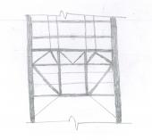
Badar (BAZ) got a reaction from UmarMakhzumi in Modelling Steel Truss with Overhang on ETABS
Check your supports. What type of supports have you assigned? Have you assigned any end releases?
-
 Badar (BAZ) got a reaction from Rizwanhanif95 in Column development length in Raft Inward or Outward
From the seismic point of view, the former is recommended by the code (ACI 318-19). See the attached:
-
Badar (BAZ) reacted to UmarMakhzumi in R.C.C Slab Failure
Wsalaam..
First, we need to understand why this happened.
1) Was this because the existing design was inadequate. -> You need to do validate existing design to check this.
2) Was this because the construction wasn't as per the design. -> I doubt you will have any construction record so you need to see photos of construction if available to make sure the lengths were right. Get some additional NDTs to confirm rebar size, spacing, cover, concrete strength to figure out the problem.
3) Based on above you, you can suggest the path forward.
Hope that helps.
-
Badar (BAZ) got a reaction from UmarMakhzumi in Crack width
Yes!
Needless to say: cracked. One also need to specify the source of reinforcement as well via "cracking analysis options".
-
Badar (BAZ) got a reaction from UmarMakhzumi in stiffness matrix from mode shape
I have a vague idea on how to approach it. But, yo should ask this question to some one in academics. Most of the practicing structural engineers do not need to do this in their projects; if you dot not do something often, then that concept goes away after period of time.
Vague Idea
for a particular mode: mass matrix x acceleration matrix + stiffness matrix x displacement matrix = 0
You can get mass, acceleration and displacement data for a particular mode and then work out stiffness matrix.
I am not sure if it will be helpful or not.
-
Badar (BAZ) got a reaction from Muhammad Hashmi in Crack width
Yes!
Needless to say: cracked. One also need to specify the source of reinforcement as well via "cracking analysis options".
-
Badar (BAZ) reacted to Osama Anwar in Slab parameters for Open Grid Steel Flooring in ETABs
I only want to investigate loads on beams and columns.
Steel gratings panel are made up of bearing bars and intermediate bars. Bearing bar orientation is perpendicular to the span (c/c distance of adjacent beams) which varies from 2'-5' so I have to subdivide slab in such a way that beams are at 5' c/c in one direction. Length of grating may be equal to span or greater than span. I have not seen it, I know this from web surfing.
I don't think it will be able to transfer moments. What do you think? I think it would act as one way. I wanted to model self weight through area element so I took mass of material as 0.
I am using membrane with E almost equal to zero WITHOUT one way option. Will it do? Isn't deck for composites?
If I am applying self loads through shell loads option i.e. unit weight equal to zero, setting the thickness won't matter. Right?
Thanks for the great explanation. Much appreciated.
Btw is there a steel frame in your profile picture? I was wondering which steel section we use as bracing in Pakistan? Angle or circular HSS or other?
-
Badar (BAZ) got a reaction from Muhammad Hashmi in Slab parameters for Open Grid Steel Flooring in ETABs
You seem to be approaching your modelling without clear and basic understanding of what constitutes as structural system in this kind of floor.
What I see, when I look at this picture is: a floor in which loads are carried directly by beams, which in turn transfer the forces to girders; beams are laterally braced by cross-members. So, you need to model your beams and girders with line elements.
And why would you take your modulus of elasticity as 0.00001? E is responsible for providing stiffness. If E is 0, it means do not have any structural member! I am sure that is not the case.
-
Badar (BAZ) got a reaction from UmarMakhzumi in Slab parameters for Open Grid Steel Flooring in ETABs
You seem to be approaching your modelling without clear and basic understanding of what constitutes as structural system in this kind of floor.
What I see, when I look at this picture is: a floor in which loads are carried directly by beams, which in turn transfer the forces to girders; beams are laterally braced by cross-members. So, you need to model your beams and girders with line elements.
And why would you take your modulus of elasticity as 0.00001? E is responsible for providing stiffness. If E is 0, it means do not have any structural member! I am sure that is not the case.
-
 Badar (BAZ) got a reaction from Hamza Irshad in Column development length in Raft Inward or Outward
Yes, surely the mechanics of force transfer makes the hook redundant if development length is available. Code's language also suggests the same; the have used the phrase " if hooks are required...".
-
Badar (BAZ) reacted to HAMMAD BASHIR in Column development length in Raft Inward or Outward
Hooks are provided for to resist seismic movement. To prevent concrete from splitting outward. It prevent slippage of steel from the concrete.
In Detailing book M. Y. H. Bangash .
-
Badar (BAZ) got a reaction from Muhammad Hashmi in Column development length in Raft Inward or Outward
Yes, surely the mechanics of force transfer makes the hook redundant if development length is available. Code's language also suggests the same; the have used the phrase " if hooks are required...".
-
Badar (BAZ) got a reaction from UmarMakhzumi in Column development length in Raft Inward or Outward
Yes, it has been prescribed for structures falling under seismic design category (SDC) D, E or F; these buildings are detailed to achieve higher ductility. The detail achieves higher ductility, so no need to do bend the column-longitudinal bars towards the centerline if ductility demands are low (structure need to satisfy the ACI 318 guidelines pertaining to SDC A,B and C for those).
-
Badar (BAZ) got a reaction from UmarMakhzumi in Column development length in Raft Inward or Outward
From the seismic point of view, the former is recommended by the code (ACI 318-19). See the attached:
-
 Badar (BAZ) got a reaction from SMAQ in ALLOWABLE LONG TERM DEFLECTION
I think you are not getting his point. He is saying that if you allow column strip deflection to be 39mm as per L/240 criteria of the code, then that deflection will be translated to a value of 52mm at the mid span of middle strip.
Explanation: For 39mm deflection, the slope of the deflected slab will be 9.3/2/.039 = 119.5 (about 1 in 120); and based on that slope, the midspan deflection will be about 12.46/2/.120 = 51.9mm.
If possible, can you share how are you calculating your long term deflections of two way slab panels?