Search the Community
Showing results for tags 'Drift'.
Found 10 results
-
Building Drift in ETABS Drift is a very complex topic in structural engineering. It involves too many factors to arrive at a suitable decision. It involves engineering judgment, the phenomenon fresh engineers might not feel. In this article, I have tried to explain what is building drift, allowable limits, ways and means to check in ETABS models and to control the excessive drift. Please keep in mind, this article is not about the building drift as far as structural science is concerned, rather this topic of drift is related to ETABS software. First of all you must be familiar with the term story drift. For convenience, I am quoting here the definitions from UBC-97 code:- STORY DRIFT is the lateral displacement of one level relative to the level above or below. STORY DRIFT RATIO is the story drift divided by the story height. 1) Maximum Limits Now what for story drift limits? What is the maximum permissible value? Well it depends upon the type of drift. Is it seismic or wind? For seismic, I will refer to UBC-97 code which in section 1630.10.2 talks about drift limits for earthquake. Now in simple words, the maximum limit for seismic drift is:- delta M shall not exceed 0.025 x story ht (if building seismic period is less than 0.7) delta M shall not exceed 0.020 x story ht (if building seismic period is equal or greater than 0.7) Important to note here is that it talks about SEISMIC drift so SEISMIC building period not the WIND period. Now delta M = Max inelastic response displacement = 0.7R delta S where R = from Table 16-N delta S = displacement from static, elastic analysis this value is read from ETABS. you multiply this value by 0.7R to get delta M This was all about seismic drift, but for wind drift code is mute. I will refer you to ASCE 2005 commentary CC.1.2 So we can understand that the limit for wind drift is "on the order of l/600 to l/400" for "common usage". This is common thing, however, in reality this figure can be up or down depending upon the ductility of cladding material and finishes. However for common usage value of l/400 is thought to be well satisfactory. Here l means story ht. The concept of drift limits is same throughout all the governing codes, and the typical limits of story height by some number is same, but obviously you have to take care of the process of calculating the wind force or seismic forces. You should not calculate wind force from one code and apply limits of another code. 2) Load Combinations Once the drift limit has been determined separately for seismic and wind forces, now is the need to check the actual drift vs the limit. Determination of actual drift depends on the load combination and the period of recurrence. If not properly calculated, this may dramatically increase or decrease the accepted drift values in model. Seismic force E is always already factored so that's the reason its factor is always 1.0 in load combinations of ACI/ASCE code. The recurrence period for seismic force is 50 years. In seismic drift we do not convert it into service seismic force. Seismic drift is checked against the direct load case of EQx, EQy etc in ETABS. For wind drift, we need to convert 50 year wind to service wind force. It has been recommended by ASCE commentary CC.1.2 To convert 50 year service wind force to 10 year service wind force it is multiplied by 0.7, as the equation says, and other gravity loads; D and 0.5L are also added. So in a nutshell we create following load combinations in ETABS to check our drift:- DRIFTWx1 = D+0.5L+0.7Wx DRIFTWx2 = D+0.5L-0.7Wx DRIFTWy1 = D+0.5L+0.7Wy DRIFTWy2 = D+0.5L-0.7Wy For seismic drift, as discussed earlier, we do not need any combination, drift will be checked just on EQx and EQy load cases only. 3) How to check in ETABS Now we have obtained both the actual drift and the drift limit, but how can we do this in ETABS easily? Well, after creating the drift combinations as discussed in step 2, we need to do as below:- For seismic drift goto File>Print Tables>Summary Report Select the file name Scroll down to the end of the page, you will find out a section about drifts, similar to this one:- It displays the max drift for each lateral load case for each story. As we want the drift for wind to be on drift load combinations and not on wind load cases, so we will not compare this wind drift without limits. In this table we are going to check just the drift values of our ETABS model for individual seismic load cases; EQx and EQy. As you noticed, this table shows us values in fraction format. For example 1/105 that becomes 0.009523809524. This 1/105 value is story drift divided by story ht. It means delta S / story ht. Now this value is delta S. First we need to convert it to delta M by multiplying it with 0.7R. Assume R here is 3.5 so delta M = 0.7 x 3.5 x 1/105 = 7/300 = 0.023333 which is less than 0.025 so safe ( if T<0.7). So instead of calculating every time by 0.7R we can check these limits in other way. If our limit is 0.025 then the limit we get is 0.025/R/0.7. Assume R=3.5. Now the values in ETABS are inverse so our limit is 0.7x3.5/0.025 = 98. In ETABS the drift is reported as 1/x where x is some number. Now as long as x (some number) is greater than 98 our limit of 0.025 x story ht is being satisfied. This way you can quickly check and compare seismic drifts. Now for the wind drifts, goto Display>Show tables, select Point displacements>Story drifts and then select only drift combinations for results. Click on and then copy the table to EXCEL. To save time you can right click on EXCEL taskbar and select maximum and minimum. Then just select the column H or I and see the maximum value that should be less than H/400 to H600 limit (0.0025 t0 0.00167). Again the values reported in ETABS are divided by story ht. http://4.bp.blogspot.com/-9qv8XKHgL8Q/UALNKflmVsI/AAAAAAAAAEQ/AwKBYWt2iys/s320/image022-773193.jpg 4) Controlling Excessive Drift Values sometimes you may face problem of excessively large values in drift tables in ETABS. Well we are not going to talk about different measures and modeling techniques to control the drift values. We are going to talk about large numbers in drift tables. Sometimes it happens that a point or node is free in the model or is connected to a NULL line or very flexible section. Drift tables for example the story drift table in wind captures the maximum displaced points. Obviously the displacement of several meters in tables is not what we are looking for. Drift values (relative) may be still okay for these points, but it requires you to check the displacement values too before checking directly the drift. Unlock the model and remove all free points, check for any discontinuity and modify your models to remove all the errors.
- 23 replies
-
- 15
-

-
- wind story drift limits ubc
- drift
- (and 1 more)
-
*SEFP Consistent Design* *UBC Seismic Drift Limits* *Doc No: 10-00-CD-0003* *Date: June 04, 2013* The goal of this tutorial is to demonstrate how to evaluate building drifts and story drifts using UBC 97 guidelines. The philosophy behind Story Drift Limits is “Deflection Control”; In UBC 97, deflection control is specified in terms of the story drift as a limit on the lateral displacement of one level relative to the level below. The story drift is determined from the maximum inelastic response, ΔM. Let’s start by defining the design-level response displacements. The elastic deflections due to strength-level design seismic forces are called design-level response displacements. These are denoted by ΔS, where the subscript ‘s’ stands for strength design. Design level response displacements are what you get out of your software, when you run analysis. Please note that structural analysis softwares may provide these values in different formats; say a percentage of height or a direct output. Well, to calculate your story drifts, first you need to find maximum inelastic response displacements from your design-level response displacements. The maximum inelastic response displacement is defined as: ΔM = 0.7RΔS Where, R is the structural system coefficient, the subscript ‘m’ in ΔM signifies that we are calculating a maximum value for the deflection due to seismic response that includes inelastic behavior. Seismic drift values are much larger than wind values. UBC uses maximum inelastic response displacements rather than the design level displacements to verify the performance of the building. Seismic drift limits are 2% & 2.5% of the story height for long and short -period buildings. For a floor to floor height of 12 feet the max., allowable inelastic drift value would be 2% of 12 feet= 0.02*12*12 in=2.88 in. For wind for a 12 story height, drift would be L/400=12*12/400 =0.36 inches, A comparison of both wind and seismic drift limits shows that earthquake inelastic displacements are quiet large compared to wind displacements. That is why proper detailing is emphasized in seismic design. When calculating ΔS for seismic, make sure: You have included accidental torsion in your analysis. Use strength design load combinations: 1.2D + 1.0E + 0.5L & 0.9D + 1.0E. You are using cracked section properties for reinforced concrete buildings. Typical values are Icr walls= 0.5EcIg, Beams = 0.5EcI g & for Columns 0.5 - 0.7 EcIg. Use a reliability/ redundancy factor= 1 to calculate seismic forces. Whenever the dynamic analysis procedure of §1631 is used, story drift should be determined as the modal combination of the story drift for each mode. Determination of story drift from the difference of the combined mode displacements may produce erroneous results because maximum displacement at a given level may not occur simultaneously with those of the level above or below. Differences in the combined mode displacements can be less than the combined mode story drift. Example: A four-story special moment-resisting frame (SMRF) building has the following design level response displacements.(See attached Image) R= 7.0, I= 1 Time period= 0.6 sec (See the attached image for Story Information) Calculate: Maximum Inelastic response displacements. Story drift in story 3 due to ΔM. Check story 3 for story drift limit. Maximum Inelastic response displacements ΔM = 0.7RΔS ΔM = (0.7) (7) ΔS = (4.9) ΔS (See the attached image for Maximum Inelastic response displacements) Story drift in story 3 due to ΔM Story 3 is located between Levels 2 and 3. Thus ΔM drift = 5.39 - 3.43 = 1.96 in. Check story 3 for story drift limit. For structures with a fundamental period less than 0.7 seconds, §1630.10.2 requires that the ΔM story drift not exceed 0.025 times the story height. For story 3: Story drift using ΔM = 1.96 in. Story drift limit = 0.025 *(12*12) in = 3.6 in. > 1.96 in. Therefore, Okay.
- 13 replies
-
- 10
-
-

-
How to overcome story drift ? If max drift value at story x is 1/40 and direction is x then what changes should be made on that story x ?
-
Hello, I am learning SAP2000. Hence it may be a general question. I have a 4*3( X and Y direction) bay frame building . While calculating the maximum story drift and the interstory drift in each direction (x and Y) which frame should we consider among those ? Each frame has a different drift. I mean the roof point on the outer frame has different displacement to that of same roof point on the inner frame ? So out of those 4 frame ( in X-direction and 3 frame in Y direction which should we consider?
-
What should be the value of maximum to average displacement ratio in multi-story building?? (as calculates in Etabs) For how much building height it is must be considered and controlled in design?? Any reference material or code will be helpful.. Thanks
-
Dear Seniors! I have modeled a 3-storeys building in 2B zone but my drift values are exceeding the maximum limits (0.02) although i increased column and beam sizes.. Kindly, suggest me what alternatives i need to consider??? Thanks!
-
AOA hope you will be fine how to calculate building joint displacement from etabs specially for EQ loading and what are the code allowable limits for that .?
-
AOA, I am getting a maximum displacement of 3 inches for a building of B+3 (total height of 52 ft) due to EQ loading in X direction. My question is that is there any code limitations/thumb rule for the lateral sway in RC buildings. ?? kindly have a look to Story displacement and story drift snap shot attached. Thanks

-
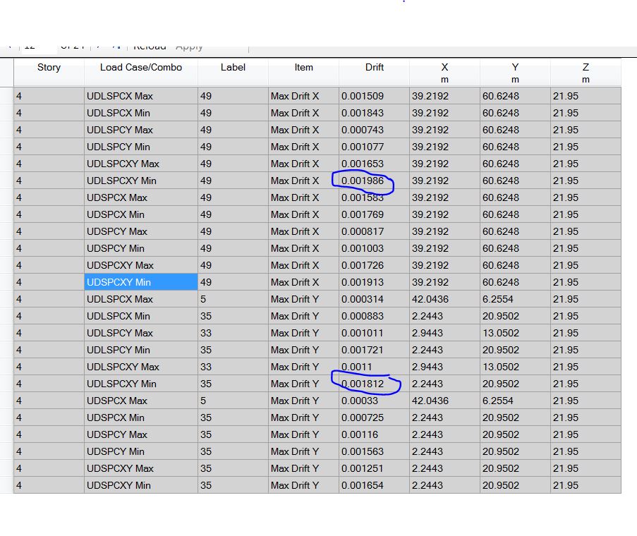
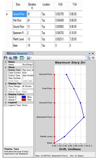
Dear all; I have prepared some procedures that in need to your evaluation according to your experience judgement. I am saying that the following procedures that I will mention will be trusted after your comments that agree or disagree. The procedure: 1. I get results from tables------> story drift as in pict.1. 2. Let us take one floor as a sample.For that floor we read the results of drift in x-direction as the maximum of all load combinations's results that contain earthquake i.e six load combinations as shown in pic.2 . 3. Do the above for y-direction. 4. As a result the for 4th floor; Drift-x = 0.001986 and Drift-y = 0.001812. 5. Now what are the values we get and how to use it. These values coming from ETABS are representing the difference in elastic displacement between the floor and the floor beneath or up divided by the floor height.(Please correct me if I am wrong). 6. Now to get the the seismic drift values from inelastic response we multiply the above drift by 0.7 *R . As an example let us say R=4.5 , then seismic drift-x =0.00625 and drift-y= 0.0057. 7. These values now are ready to compare with ACI code limitations, Assuming fundamental period of structure=0.5 second: story seismic drift limit =2.5% * story height 8. As you may see our story drifts either in x or in y are less than 2.5 %. Regards
-
 Hello everyone, I am looking for some answers to simple questions like 1. What is the inter story drift limit for steel columns , and what is the maximum deflection allowed at the mid span of the column which has axial load and lateral loading as well ? 2. How we decide the end at which moment need to be released and which one like M22 or M33? Does this depends upon the support end and type of support? 3. What is the difference between the pin support and fix support in terms of its application to the model? As lateral meaning is not required its the sense that on which basis we decide that oke we donot model pin support and assign fix support to the model. and then when we are designing base connection like base plate and anchor bolt and position of anchors on the base plate. Does this all only gives us freedom in the fixity of structure at the base like we are free on locating the suitable position for anchors on the base plate or it has to do something else as well ? 4. What about the wind loading? if we calculate the wind load manually and then apply it as a lateral load to the whole structure is ok or we just go as making the areas around the nodes and apply the load only to the nodes and then chk the deformation. What about the wind analysis we do by the help of software how accurate are they as the deformation due to wind is nothing in many cases if you see the analysis report or table...