Jump to content
  • Welcome to SEFP!

    Welcome!

    Welcome to our community forums, full of great discussions about Structural Engineering. Please register to become a part of our thriving group or login if you are already registered.

Lecture Notes/Comprehensive Textbook: Reinforced Concrete Design by Dr. Wael Hassan


Dr. Wael Hassan
 Share

Recommended Posts

بسم الله الرحمن الرحيم


I provided the book in three formats for easy access in the Google Drive links below

The Full Book in a Single File:

https://drive.google.com/file/d/1gSew3TaAPpEku3tW9fcC4QJ72PaVXBao/view?usp=sharing

Separate Book Chapters Files:

https://drive.google.com/drive/folders/1tueeYgieZx8zWMsmp3g1enoqPyna6Bp8?usp=sharing

Separate Book Subtopic Files:

https://drive.google.com/drive/folders/1ljDq3oRMWCaEz2x-QB5kVNB8GB32d0ke?usp=sharing


Here is another link in Internet Archive

https://archive.org/details/full-book-concrete-design-dr.-wael-hassan-2023


Preface

I have been occupied for long time with the idea of writing a professional textbook on the design of concrete structures that presents this challenging subject in a simplified way, yet technically rigorous, accessible to most civil engineering students, even those not to specialize as structural engineers. I had intended that the book reflects my expertise in structural engineering, specifically concrete design, spanning more than 20 years of professional practice, research, and teaching. With that in mind, I developed over the years sets of lecture notes on reinforced concrete design that I used in various academic roles from teaching assistant to associate professor to teach undergraduate students in higher education institutions in the Middle East and North America


This “book” is intended as a humble contribution in the field of structural design of reinforced concrete to make it more approachable, handy, and useful to undergraduate students and practicing structural engineers. It represents my set of lecture notes on concrete design developed over the period of eight years. However, most of the material presented, especially on the analysis and systems, can be useful in concrete design using any building code, with proper modifications according to local codes, since the theoretical basis used is common in many aspects among various codes


My intent was to wait until I rewrite these lecture notes, with additional formal discussions, in a formal textbook format and assign a publisher to edit and disseminate that textbook professionally. However, given the substantial size of the material and my current academic and professional commitments, this project can take a few more years to be completed in the presentable way I envisioned. I felt guilty to hold back this knowledge further until formal publication although it can help many students and engineers until then, thus I am presenting these lecture notes as is with my handwriting and manual drawings in this “book,” with the intent of revising, upgrading and publishing it professionally in the future. Please refer to the remark in the Introduction chapter for details about the consistency of this book with the latest version of the Egyptian Code ECP 203-2020. The material in its current format is generally self-contained and it helped thousands of civil engineering students and practicing engineers learn concrete design successfully.


I retain my publishing rights of this material for the sole intention of publishing the textbook in a more formal manner in the future; however, I grant the right to any individual to use the book for academic and educational purposes or professional design purposes without my permission. I further grant the right to any individual to post this material as is on the Internet and to distribute as is electronically or in print. The only restriction is to reproduce the material in part or whole in a different format without proper citation to use for commercial purposes without permission.


Wael M. Hassan, Ph.D., P.E., S.E., F.ACI, F.ASCE, F.SEI

Associate Professor of Structural Engineering


TABLE OF CONTENTS

PREFACE


ACKNOWLEDGEMENT


CHAPTER 1: Introduction

Overview

 Organization of the "Book"


CHAPTER 2: Design of Reinforced Concrete Beams

Loads on RC Beams

 Loads on RC Beams Solved Problems

 Straining Actions/Internal Forces of RC Beams

 Fundamentals of Reinforced Concrete Design/Stages of Concrete Cracking

 Ultimate Limit State Design Method

 Ultimate Limit State Design Solved Problems

 Flexural Design of RC Beams

 Flexural Design of RC Beams Solved Problems

Design of Continuous Beams

 Shear Design of Concrete Beams

Torsion Design of RC Beams

 Serviceability Limit States I: Deflection Calculations

 Serviceability Limit States II: Crack Control

 Shear Friction Design

 Design of Short Cantilevers

 Design of Deep Beams

 Problems on RC Beam Design


CHAPTER 3: Design of Reinforced Concrete Slabs

 Design of RC Solid Slab and Beam System

 RC Solid Slab Design Solved Problems

 RC Paneled Beam System

 RC Paneled Beams Solved Problems

 Design of Hollow Block Slab Systems

 Hollow Block Slabs: Commentary for Students

 Solved Problems on Hollow Block Slabs

 Design of RC Flat Plate and Flat Slab Systems

 Solved Problems on RC Flat Slabs

 Design of RC Stairs

 RC Stairs Reinforcement Details and Solved Problems

 Sample Exam Problems on RC Stairs

 Sample Exam Problems and Ideas on Floor Slabs

 Summary Notes on RC Slab Design and Exam Problems

 Unsolved Practice Problems on RC Slabs


CHAPTER 4: Design of Reinforced Concrete Columns

 RC Column Design

 Column Design Example

Column Design Summary and Commentary for Students

 Eccentric Section Design

 Eccentric Section Commentary for Students

 RC Columns Design Tips

 RC Columns Problems


CHAPTER 5: Foundation Design

 Design of Isolated Footings

 Solved Problems on Isolated Footing Design


CHAPTER 6: Design of Reinforced Concrete Frames

Reinforced Concrete Frames Design

 Reinforced Concrete Frames Solved Problems and Exams

 Sample Practice Problems


CHAPTER 7: Design of Reinforced Concrete Halls

 Design of RC Halls: North Light Roof Systems

 Commentary for Students on RC Hall Design


CHAPTER 8: Design of Concrete Tanks and Water Structures

Crack Control of Concrete Structures

 Solved Problems on RC Crack Control

 Design of Rectangular RC Tanks

 Design of Circular RC Tanks

 Design of RC Tanks Rested on Soil

 Solved Problems on RC Tank Design

 Practice Problems


CHAPTER 9: Design of RC Buildings for Lateral Loads

 Design for Lateral Loads


CHAPTER 10: Design of Prestressed Concrete Structures

 Prestressed Concrete Design

 Prestressed Concrete Losses

 Prestressed Concrete Anchorage


CHAPTER 11: Design of Repair and Retrofit of RC Structures

 Cracks in RC Structures

 Concrete Structures Assessment Tests

 Repair and Retrofit of Concrete Slabs

 Repair and Retrofit of Concrete Beams

 Repair and Retrofit of Concrete Columns


أهدي هذا العمل الي أحبائي طلاب الهندسة المدنية والانشائية والمعمارية وهندسة التشييد وزملائي المهندسين و كذلك أساتذة الهندسة الانشائية بالجامعات. أسأل الله أن ينفع به ويجعله خالصا لوجهه. ولا تبخلوا في الدعاء لي ان وجدتم فائدة في هذا الكتاب.

الكتاب يشمل جميع موضوعات تصميم الخرسانة المسلحة بطريقة ميسطة بدءا من الأحمال والنظم الانشائية حتي الأساسات وتدعيم المنشات في أكثر من 2000 صفحة.


لقد شغلتني منذ فترة طويلة فكرة تـأليف كتاب دراسي احترافي في تصميم المنشآت الخرسانية بطريقة مبسطة، ولكنها محكمة من الناحية الفنية، مما يجعل المادة في متناول معظم طلاب الهندسة المدنية، حتى أولئك الذين لا ينوون التخصص في الهندسة الإنشائية. كنت أنوي أن يعكس الكتاب خبرتي في الهندسة الإنشائية، وتحديدًا تصميم الخرسانة الإنشائية، والتي تمتد لأكثر من 20 عامًا من الممارسة المهنية والبحث والتدريس. ومن هذا المنطلق، قمت على مر السنين بتأليف وتطوير مجموعتين من المحاضرات في تصميم الخرسانة المسلحة، استخدمتهما لتدريس الطلاب في جامعات الشرق الأوسط وأمريكا على مدار تاريخي الأكاديمي منذ درجة مساعد تدريس حتى أستاذ مشارك في الهندسة الإنشائية.


يهدف هذا "الكتاب" إلى تقديم مساهمة متواضعة في مجال التصميم الإنشائي للخرسانة المسلحة لجعله أكثر سهولة وتناولا وفائدة للطلاب الجامعيين والمهندسين الإنشائيين. والكتاب يمثل مجموعة محاضراتي في التصميم الخرساني ، والتي طورتها على مدار ثمان سنوات. معظم المادة المقدمة، وخاصة فيما يتعلق بالأنظمة الإنشائية والتحليل، يمكن أن تكون مفيدة في التصميم الخرساني باستخدام أي كود بناء، مع التعديلات المناسبة حسب الكود المحلي، حيث أن الأساس النظري المستخدم مشترك في العديد من الجوانب بين مختلف الأكواد المعتمدة.


وقد كنت أنوي الانتظار حتى أعيد كتابة هذه المحاضرات وأحدثها، مع إثرائها بمناقشات ومواد توضيحية إضافية، في نسق كتاب احترافي واختيار ناشر لتحرير ذلك الكتاب ونشره بشكل جذاب. ولكن هذا المشروع، ونظرًا لضخامة حجم المادة والتزاماتي الأكاديمية والمهنية الحالية، قد يستغرق بضع سنوات أخرى حتى يكتمل بالطريقة التي تصورتها. ولذلك فقد شعرت بالذنب لتأخير نشر هذا العلم حتى ييسر الله النشر الرسمي رغم أنه يمكن أن يساعد العديد من الطلاب والمهندسين حتى ذلك الحين، وبالتالي فإنني أقدم هذه المحاضرات كما هي بخط يدي ورسومي التوضيحية اليدوية في هذا "الكتاب"، مع نيتي مراجعتها وتحديثها ونشرها بشكل احترافي في المستقبل إن شاء الله. وقد ساعدت هذه المحاضرات على مدار السنوات آلافا من طلاب الهندسة المدنية والمهندسين الممارسين على تعلم تصميم الخرسانة الإنشائية بنجاح.


يرجى العلم بأنني أحتفظ بحقوق نشر هذه المادة لغرض وحيد هو نشر الكتاب بطريقة أكثر رسمية في المستقبل؛ ومع ذلك، فأنا أمنح الحق لأي فرد في استخدام الكتاب للأغراض الأكاديمية والتعليمية أو لأغراض التصميم الاحترافي دون إذني. كما أمنح الحق لأي فرد في نشر هذه المادة كما هي على الإنترنت وتوزيعها كما هي إلكترونيًا أو مطبوعة. لكن القيد الوحيد على الاستخدام هو إعادة إنتاج المادة جزئيًا أو كليًا بتنسيق مختلف دون الاقتباس المناسب لاستخدامها لأغراض تجارية دون إذن.


دكتور مهندس: وائل حسن

أستاذ مشارك في الهندسة الإنشائية

Book Sharing_2.pdf

Link to comment
Share on other sites

Create an account or sign in to comment

You need to be a member in order to leave a comment

Create an account

Sign up for a new account in our community. It's easy!

Register a new account

Sign in

Already have an account? Sign in here.

Sign In Now
 Share

  • Recently Browsing   0 members

    • No registered users viewing this page.
  • Our picks

    • Hi there,
      I am interested in performing "Performance Based Design" for a 20 story building. 
      I'll be performing "Non-Linear Static Pushover Analysis" for my model. Until now, I have decided to go with "Displacement Co-efficient method". I will be using ETABS 2017 for performing Pushover Analysis. While assigning plastic hinges, I have an option of using ASCE 41-17 (Seismic Evaluation and Retrofit of Existing buildings". I would like to know what would be a better estimate for relative distances for plastic hinges in case of beams, columns. Any input concerning assignment of hinges to beams, columns and shear walls is highly appreciated. Normally it's taken 0.05 and 0.95 or 0.1 and 0.9. What's your opinion on this?
      Secondly, it would be great if someone can recommend me a book or some good source to understand how to characterize building using performance levels. Any sort of help is appreciated.
      I have recently graduated and joined a structural design firm, so kindly guide me, considering me a beginner.

       
      • 2 replies
    • *SEFP Consistent Design*<br style="background-color:#ffffff; color:#272a34; font-size:14px; text-align:start">*Pile Design*<br style="background-color:#ffffff; color:#272a34; font-size:14px; text-align:start">*Doc No: 10-00-CD-0007*<br style="background-color:#ffffff; color:#272a34; font-size:14px; text-align:start">*Date: April 16, 2018*

      1.1. FUNCTION OF JOINT

      Beam-column joint must transfer the forces, such as moment, shear and torsion, transferred by the beam to the column so that the structure can maintain its integrity to carry loads for which it is designed.

      Another function of the beam-column joint is to help the structure to dissipate seismic forces so that it can behave in a ductile manner.

      1.2.WHY DO WE CARE

      During an extreme seismic event, the code-based structure is expected to maintain its load-carrying capacity for gravity loads even after the structure deforms into inelastic range so that it does not pose any life safety hazard. Hence, the joint can go through significant degradation of strength and stiffness, and if it fails in shear, or anchorage, the life-safety objective of code cannot be achieved.

      1.3.CONSEQUENCES OF FAILURE


      1.4.THINGS TO CONSIDER FOR BEAM COLUMN JOINT

      Longitudinal bars of beams, or slab, must be able to develop their yield stress, so that the beam/slab can transfer moment to joint. It means that longitudinal bars must have adequate development length for hooked bars. This implies that the size of the column must be such that bars can develop their tensile forces. If bars can transfer moment, they can also transfer shear as far as monolithic construction is concerned.


      The shear strength of the joint must enable the transfer of moment and shear through it.


      The joint should be Constructible: Congestion of reinforcement is the main concern.

      1.5.DESIGN SHEAR FOR BEAM COLUMN JOINT

      The design shear for beam-column joint depends upon the relative strength of beam and column at the joint.

       
      • 4 replies
    • *Comments/Observations regarding modelling in ETABS*

      *Doc No: 10-00-CD-0006*

      *Date: May 06, 2017*

      Some of the observations made during extraction of results from ETABS (v 9.7.4), for design of reinforced concrete members, are being share in this article.,

      1) Minimum Eccentricity

      ETABS always considers the minimum eccentricity for selecting the design moment of columns irrespective of the probable behavior of the column, whether short or long column. See section 10.10.6.5 and its commentary of ACI 318-08 which deals with minimum eccentricity of long columns. You should always check the design moments that ETABS uses for columns if you want to bring down the cost of construction.

      2) Unbraced/ Braced Preference

      ETABS always performs analysis of frame as if it is un-braced. You should investigate if the storey under consideration is braced, or un-braced (10.10.5.2), and decide appropriate design moments of columns.

      3) Time Period

      ETABS has a tendency to select a time period of the building that is considerably less than the value obtained by the approximate method, Method A, of the section 1630.2.2  of UBC 97. To quote the FEMA 451 document: ''Because this formula is based on lower bound regression analysis of measured building response in California, it will generally result in periods that are lower (hence, more conservative for use in predicting base shear) than those computed from a more rigorous mathematical model". So, there is no need to use the value of time period that is lot less than Ta. One should always check the time period used by the software; ETABS can overestimate the seismic force by more than 2 times.

      Visit the forum link to read the complete article.
      Link: http://www.sepakistan.com/topic/2300-commentsobservations-regarding-modelling-in-etabs/
      • 0 replies
    • The minimum amount and spacing of reinforcement to be used in structural floors, roof slabs, and walls for control of temperature and shrinkage cracking is given in ACI 318 or in ACI 350R. The minimum-reinforcement percentage, which is between 0.18 and 0.20%, does not normally control cracks to within generally acceptable design limits. To control cracks to a more acceptable level, the percentage requirement needs to exceed about 0.60% (REFRENCE ACI COMMITE REPORT 224R-01)


      So according to above statement , should we follow 0.60%, to be on more safe side??


      • 12 replies
    • Dear Sir/Madam,

      This email is an invitation for the participation in the First South Asia Conference on Earthquake Engineering (SACEE-2019) which will be held on 21-22 February 2019 in Karachi, Pakistan. This conference is the inaugural event in this series of conferences which has been constituted under the auspices of South Asia Earthquake Network (SHAKE). The organisers of the conference include NED University, University of Porto, University of Fuzhou, University Roma Tre and Institution of Engineers Pakistan. The conference website can be visited at http://sacee.neduet.edu.pk/.

      Please note that world leading earthquake engineering experts have confirmed their participation in the conference. These include Prof Abdelkrim Aoudia (Italy), Prof Alper Ilki (Turkey), Dr Amod Mani Dixit (Nepal), Prof Bruno Briseghella (Italy), Prof George Mylonakis (UK), Prof Khalid Mosalam (USA), Prof Humberto Varum (Portugal) and many others. The presence of these distinguished experts allows you to exchange your work/issues with them and discuss possibility of any future collaboration. Please note that participation in the conference is strictly based on registration. Early registration in different categories at reduced rates are available till 10 December 2018. Please visit the conference website to see the details and the link for registration.

      If there are any queries, please do not hesitate to contact the Conference Secretary at the following address

      Prof. Muhammad Masood Rafi
      Conference Secretary- SACEE-2019
      Chairman
      Department of Earthquake Engineering
      NED University of Engineering & Technology Karachi, Pakistan.
      Phone: 0092-21-992-261261 Ext:2605
      Email: rafi-m@neduet.edu.pk
    • What is the Minimum reinforcement For Precast Pile  according to different codes (ACI,BS)??  Pile length is 40 times of pile least dimension . 
      • 1 reply
    • Dear members, I am working on a 10 storied rcc factory building with one basement,  where floor loads are in general 125 psf(Live) . but there are 2 warehouse in the building at ground floor & 10th floor where the Live load of stacked materials are 450psf. I have modeled it and analysed in ETABS. After analysis, seeing the floor displacement for seismic load,  i am in big shock to see the pattern. the displacement pattern suddenly increased hugely & then got normal . if the warehouse load created problem, then why it effected only Ground floor level, not the 10th floor! Please tell me how can i solve it. 
      • 1 reply
    • Asalamualaikum all,

      I have columns which are conflicting with the underground water tank as shown in figure.
       

      So I have decided to make underground water tank base slab as a footing for column. So I import etabs model to safe and just take uniform water load on base slab and point load from columns.

      This is the residential house. The BC is 2tsf. But SAFE is showing tension on the base slab and the thickness from punching is 30''. I believe that thickness is too high. What can be the error? Is this approach is correct for design base slab of ugwt to carry load of two edge columns?
      • 11 replies
    • SAFE perform iterative uplift analysis,any one having experience how to check the results of this analysis???what is the purpose and scope of this analysis???
      • 15 replies
    • Shear wall design
      AOA 

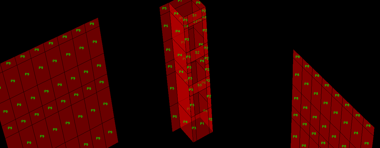
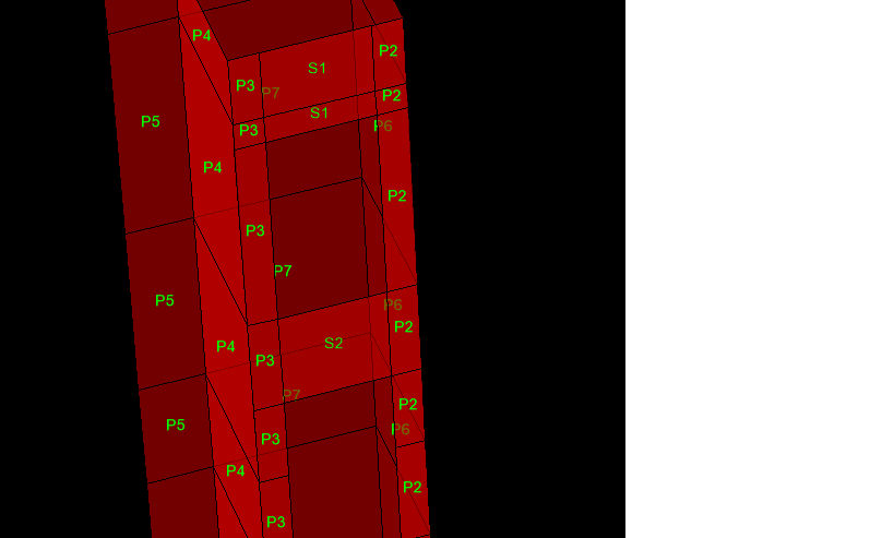
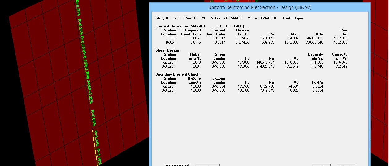
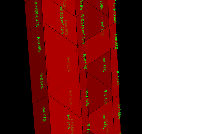
      i am facing problems in shear wall design .what are the pier and spandral ?what will be the difference when we assign pier or spandral? without assigning these the shear wall design is incomplete .

      i am taking about etabsv16

      someone have document about shear wall design plz provide it 

      thank you

       
      • 13 replies
  • Tell a friend

    Love Structural Engineering Forum Of Pakistan? Tell a friend!
  • Recent Discussions

  • Latest Forum and Club Posts

    • ETABS has various options i.e., Diaphragm Max over Avg Drifts, Story Max over Avg Displacements, Story Max over Avg drifts (Go to display tables> analysis results> joint output> displacement> the options area available here) I noticed some people do this torsional sensitivity check and calculation of torsional amplification factor (Ax and Ay) based on story drift and not on story displacements... the results from each approach gets different ??? also there is another option with Diaphragm  so what's the correct approach ??? and how do we know actually what points ETABS has considered for calculation of max/min displacement or drifts.  
    • I am working on a high rise building (overall 69 stories, 10 stories of carpark, transfer slab at level 12) located in a very low seismic zone (PGA 5%g). The building first mode is translational (i considered Ux, Uy and Uz tables for this classification) and 2nd mode is torsional followed by 3rd mode again in translational.  The modal mass participation ration as shown below. I considered the default 12 modes and getting the required overall 90 percent mass participation both in X and Y direction (Sum Ux and also Sum Uy) but didnt consider the SumUz or ther SUm Rx,Ry and Rz. Is this important ??? I understand that ideally the first 2 modes should be translational followed by torsional mode and this can be achieved with proper structural distribution of elements on the floor plans however for this building the design was freeze and the design team want to proceed. After the response spectrum analysis, i showed them that the higher reinforcement in column and shear walls are resulting from this torsional behavior in 2nd mode. My question is that we have incorporated additional reinforcement tin these shear walls and columns however the slab diaphragm needs any attention ??? or any other element like designing diaphragm particularly at the transfer level to ensure that it receives this torsion and transfer safely to shear walls and columns ??    
    • I am working on a multi tower building with a common podium (Fig 1). The initial ETABS model  wasn't built using multiple tower option however during the seismic design incorporation, i activated this "Multiple tower" option in ETABS and accordingly set podium to T1 and T2 and T3 for the remaining two towers (Fig 2). Afterwards i partially exported the towers and performed the analysis to get story forces from individual tower models. These forces were finally added as user defined seismic load in the full complete model (Fig3) As mentioned above that not to use ELF base shear, i initially thought it shouldn't be an issue. However later after analyzing the complete full model with multiple towers i realized, that it  almost showed double base shear from ELF in case we go for automatic seismic load (based on code) compared to manually applying the story forces on the towers (Fig 4). I am not sure if its some modelling mistake and trying to figure out why there is much different in static load case however the response spectrum from both models show minor difference         
    • Yes, as the approximate period is simplified and often conservative compared to more accurate one obtained from modal analysis which reflects actual stiffness, mass distribution, and geometry of structure
    • @Wajahat Latif Can you further elaborate on the above point 
    • Can share and elaborate the different load combos required for the towers which are resting on a common podium and how these are different in case a seismic joint is there ?? Also what design consideration have to be taken for the diaphragm at top of podium where the towers are resting ??As i believe that out of phase movement for the 2 towers will generate high internal forces at the podium diaphragm. Does ETABS automatically considers them or we need to manually define some combinations for such scenarios ???
    • what is our ultimate goal by making reduction in members stiffnesses in softwares ?? i know the concept but i do not know the sense behind this in terms of the practical advantages will get after doing this and what will happen if we did not .
    • hi engineers , May i know why we have to rely on meshing to govern our programe results and hence the design , if result is going to be affected by meshing how colud we get the accurate result for safe design ??? and to what limit can we depend on meshing ?
    • Just use excel. Make a simple worksheet listing bar dia, number, length for each element. Bar weight tables are available online.  OR If its a building and you have the Etabs model. Run the detailer, it will give weight of steel required for each floor or member wise. Staad Pro also gives total steel weight and concrete volume for the model
×
×
  • Create New...

Important Information

By using this site, you agree to our Terms of Use and Guidelines.