-
Welcome to SEFP!

-
Recently Browsing 0 members
- No registered users viewing this page.
-
Our picks
-
Performance Based Seismic Design
Howard Roark posted a topic in General Discussion,
Hi there,
I am interested in performing "Performance Based Design" for a 20 story building.
I'll be performing "Non-Linear Static Pushover Analysis" for my model. Until now, I have decided to go with "Displacement Co-efficient method". I will be using ETABS 2017 for performing Pushover Analysis. While assigning plastic hinges, I have an option of using ASCE 41-17 (Seismic Evaluation and Retrofit of Existing buildings". I would like to know what would be a better estimate for relative distances for plastic hinges in case of beams, columns. Any input concerning assignment of hinges to beams, columns and shear walls is highly appreciated. Normally it's taken 0.05 and 0.95 or 0.1 and 0.9. What's your opinion on this?
Secondly, it would be great if someone can recommend me a book or some good source to understand how to characterize building using performance levels. Any sort of help is appreciated.
I have recently graduated and joined a structural design firm, so kindly guide me, considering me a beginner.
-
-
- 2 replies

-
-
Beam Column Joint
Badar (BAZ) posted a topic in Journal/ Articles/ Tutorials,
*SEFP Consistent Design*<br style="background-color:#ffffff; color:#272a34; font-size:14px; text-align:start">*Pile Design*<br style="background-color:#ffffff; color:#272a34; font-size:14px; text-align:start">*Doc No: 10-00-CD-0007*<br style="background-color:#ffffff; color:#272a34; font-size:14px; text-align:start">*Date: April 16, 2018*
1.1. FUNCTION OF JOINT
Beam-column joint must transfer the forces, such as moment, shear and torsion, transferred by the beam to the column so that the structure can maintain its integrity to carry loads for which it is designed.
Another function of the beam-column joint is to help the structure to dissipate seismic forces so that it can behave in a ductile manner.
1.2.WHY DO WE CARE
During an extreme seismic event, the code-based structure is expected to maintain its load-carrying capacity for gravity loads even after the structure deforms into inelastic range so that it does not pose any life safety hazard. Hence, the joint can go through significant degradation of strength and stiffness, and if it fails in shear, or anchorage, the life-safety objective of code cannot be achieved.
1.3.CONSEQUENCES OF FAILURE
1.4.THINGS TO CONSIDER FOR BEAM COLUMN JOINT
Longitudinal bars of beams, or slab, must be able to develop their yield stress, so that the beam/slab can transfer moment to joint. It means that longitudinal bars must have adequate development length for hooked bars. This implies that the size of the column must be such that bars can develop their tensile forces. If bars can transfer moment, they can also transfer shear as far as monolithic construction is concerned.
The shear strength of the joint must enable the transfer of moment and shear through it.
The joint should be Constructible: Congestion of reinforcement is the main concern.
1.5.DESIGN SHEAR FOR BEAM COLUMN JOINT
The design shear for beam-column joint depends upon the relative strength of beam and column at the joint.
-
-
- 4 replies
-
-
Comments/Observations regarding modelling in ETABS
Badar (BAZ) posted a topic in Journal/ Articles/ Tutorials,
*Comments/Observations regarding modelling in ETABS*
*Doc No: 10-00-CD-0006*
*Date: May 06, 2017*
Some of the observations made during extraction of results from ETABS (v 9.7.4), for design of reinforced concrete members, are being share in this article.,
1) Minimum Eccentricity
ETABS always considers the minimum eccentricity for selecting the design moment of columns irrespective of the probable behavior of the column, whether short or long column. See section 10.10.6.5 and its commentary of ACI 318-08 which deals with minimum eccentricity of long columns. You should always check the design moments that ETABS uses for columns if you want to bring down the cost of construction.
2) Unbraced/ Braced Preference
ETABS always performs analysis of frame as if it is un-braced. You should investigate if the storey under consideration is braced, or un-braced (10.10.5.2), and decide appropriate design moments of columns.
3) Time Period
ETABS has a tendency to select a time period of the building that is considerably less than the value obtained by the approximate method, Method A, of the section 1630.2.2 of UBC 97. To quote the FEMA 451 document: ''Because this formula is based on lower bound regression analysis of measured building response in California, it will generally result in periods that are lower (hence, more conservative for use in predicting base shear) than those computed from a more rigorous mathematical model". So, there is no need to use the value of time period that is lot less than Ta. One should always check the time period used by the software; ETABS can overestimate the seismic force by more than 2 times.
Visit the forum link to read the complete article.
Link: http://www.sepakistan.com/topic/2300-commentsobservations-regarding-modelling-in-etabs/-
-
- 0 replies
-
-
Minimum Reinfocement Criteria For Crack Control
abdulqadeer29 posted a topic in Concrete Design,
The minimum amount and spacing of reinforcement to be used in structural floors, roof slabs, and walls for control of temperature and shrinkage cracking is given in ACI 318 or in ACI 350R. The minimum-reinforcement percentage, which is between 0.18 and 0.20%, does not normally control cracks to within generally acceptable design limits. To control cracks to a more acceptable level, the percentage requirement needs to exceed about 0.60% (REFRENCE ACI COMMITE REPORT 224R-01)
So according to above statement , should we follow 0.60%, to be on more safe side??
-
-
- 12 replies
-
-
First South Asia Conference on Earthquake Engineering (Karachi)
Fatima Khalid posted a topic in General Discussion,
Dear Sir/Madam,
This email is an invitation for the participation in the First South Asia Conference on Earthquake Engineering (SACEE-2019) which will be held on 21-22 February 2019 in Karachi, Pakistan. This conference is the inaugural event in this series of conferences which has been constituted under the auspices of South Asia Earthquake Network (SHAKE). The organisers of the conference include NED University, University of Porto, University of Fuzhou, University Roma Tre and Institution of Engineers Pakistan. The conference website can be visited at http://sacee.neduet.edu.pk/.
Please note that world leading earthquake engineering experts have confirmed their participation in the conference. These include Prof Abdelkrim Aoudia (Italy), Prof Alper Ilki (Turkey), Dr Amod Mani Dixit (Nepal), Prof Bruno Briseghella (Italy), Prof George Mylonakis (UK), Prof Khalid Mosalam (USA), Prof Humberto Varum (Portugal) and many others. The presence of these distinguished experts allows you to exchange your work/issues with them and discuss possibility of any future collaboration. Please note that participation in the conference is strictly based on registration. Early registration in different categories at reduced rates are available till 10 December 2018. Please visit the conference website to see the details and the link for registration.
If there are any queries, please do not hesitate to contact the Conference Secretary at the following address
Prof. Muhammad Masood Rafi
Conference Secretary- SACEE-2019
Chairman
Department of Earthquake Engineering
NED University of Engineering & Technology Karachi, Pakistan.
Phone: 0092-21-992-261261 Ext:2605
Email: rafi-m@neduet.edu.pk-
-
- 1 reply
-
-
Minimum reinforcement For Precast Pile
Dr Yueh posted a topic in Foundation Design,
What is the Minimum reinforcement For Precast Pile according to different codes (ACI,BS)?? Pile length is 40 times of pile least dimension .-
- 1 reply
-
-
ETABS model for factory building
Palash Engr posted a topic in Concrete Design,
Dear members, I am working on a 10 storied rcc factory building with one basement, where floor loads are in general 125 psf(Live) . but there are 2 warehouse in the building at ground floor & 10th floor where the Live load of stacked materials are 450psf. I have modeled it and analysed in ETABS. After analysis, seeing the floor displacement for seismic load, i am in big shock to see the pattern. the displacement pattern suddenly increased hugely & then got normal . if the warehouse load created problem, then why it effected only Ground floor level, not the 10th floor! Please tell me how can i solve it.-
- 1 reply
-
-
Underground water tank base slab as a foundation
Fatima Khalid posted a topic in Foundation Design,
Asalamualaikum all,
I have columns which are conflicting with the underground water tank as shown in figure.
So I have decided to make underground water tank base slab as a footing for column. So I import etabs model to safe and just take uniform water load on base slab and point load from columns.
This is the residential house. The BC is 2tsf. But SAFE is showing tension on the base slab and the thickness from punching is 30''. I believe that thickness is too high. What can be the error? Is this approach is correct for design base slab of ugwt to carry load of two edge columns?-
- 11 replies
-
-
Safe Iterative Uplift Analysis
asadishaq posted a topic in Software Issues,
SAFE perform iterative uplift analysis,any one having experience how to check the results of this analysis???what is the purpose and scope of this analysis???-
-
- 15 replies
-
-
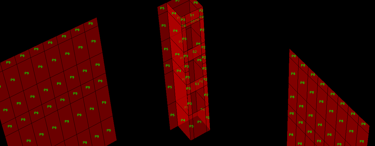
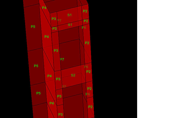
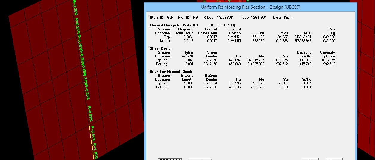
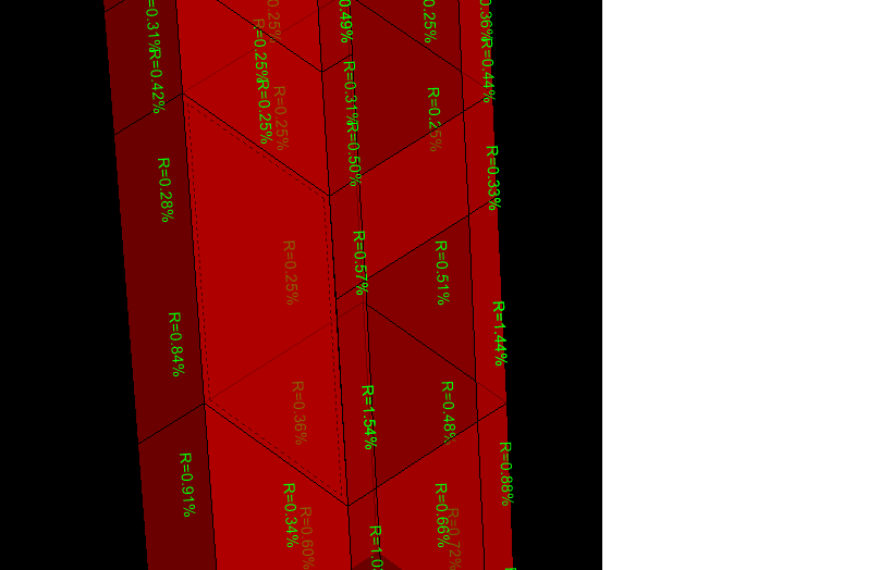
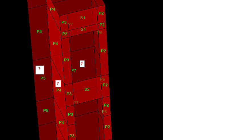
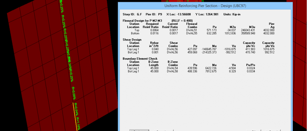
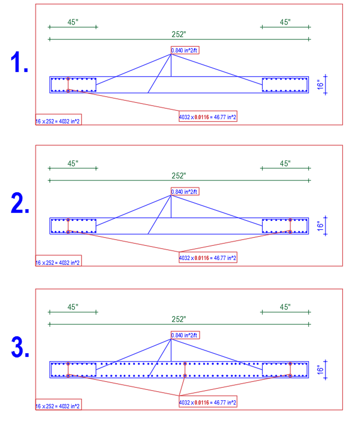
Shear wall design
farooqbro posted a topic in Concrete Design,
AOA
i am facing problems in shear wall design .what are the pier and spandral ?what will be the difference when we assign pier or spandral? without assigning these the shear wall design is incomplete .
i am taking about etabsv16
someone have document about shear wall design plz provide it
thank you
-
-
- 13 replies

-
-
-
Tell a friend


-
Similar Content
-
-
Recent Discussions
-
-
Latest Forum and Club Posts
-
 AA. Usage pf Circular Hollow Sections (CHS), Rectangular Hollow Sections (RHS) & Square Hollow Sections (SHS) is very common in steel construction industry, for Parking Sheds, canopies, etc. A brochure containing reliable structural information regarding the sizes, dimensions & weights of CHS, RHS & SHS available in Pakistan, can be very useful for local structural engineers dealing with structural steel design. Download link of Such a brochure, listing hollow sections conforming to several ASTM & other standards, is being shared here for the benefit of all those interested. Regards.
 -

By MalikMemon004 · Posted
I am designing a G+2 factory building founded on dense sandy soil as per our geotechnical investigation report. Load considered: (As Client was not sure about the purpose of use) Live Load on Slab= 3.0 kN /m2 Dead Load on Slab= 1.5 kN/m2 (other then Self weight) Grid Spacing: 27'9"x21'3" Plot Dimensions: 56'x165' Characteristic Load on Columns: (decisive case) Dead Load: 1900 kN Live Load: 950 kN The report recommended bearing capacits: Isolated Footing: 160 kPa at 2.0m depth Settelment within 25 mm Raft foundation 300 kPa at 2.0 m below existing ground level (EGL), With the column loads of around 2800 kN and grid spacing isolated footings would require very large foundation sizes leaving little or no clearance between footings and cause overlap issues. Therefore i decided to go for raft foundation. However, the site condition is such that: The EGL (existing ground level) in the report corresponds to be the site’s current level +0.0 m, while the outer road level is about +0.9 m higher. Our finished factory floor will be at +1.5 m. Now i am evaluating two options: Option A – Construct the raft foundation at the recommended -2.0 m below EGL (per the GI report), then build up columns, cast a plinth beam at the raised level, backfill up to the required ground/floor level, and finally prepare a floor over the compacted backfill. Option B – Raise the site to match the road level using engineered, well-compacted backfill, and then construct the raft foundation directly at the new raised ground level, allowing the raft slab itself to serve as the factory floor. I want to understand: Which option is more technically sound and economical considering bearing capacity, settlement control, and long-term performance? Is placing the raft on engineered backfill (Option B) acceptable practice if compaction and quality control are ensured, or is it safer to strictly follow the geotechnical recommendation (Option A)? Any insights or experience-based advice on this choice would be highly appreciated. Furthermore: Are the load assumed too conservative? Kind Regards Abdul Malik -

By Zain Saeed · Posted
ETABS has various options i.e., Diaphragm Max over Avg Drifts, Story Max over Avg Displacements, Story Max over Avg drifts (Go to display tables> analysis results> joint output> displacement> the options area available here) I noticed some people do this torsional sensitivity check and calculation of torsional amplification factor (Ax and Ay) based on story drift and not on story displacements... the results from each approach gets different ??? also there is another option with Diaphragm so what's the correct approach ??? and how do we know actually what points ETABS has considered for calculation of max/min displacement or drifts. -
By Zain Saeed · Posted
I am working on a high rise building (overall 69 stories, 10 stories of carpark, transfer slab at level 12) located in a very low seismic zone (PGA 5%g). The building first mode is translational (i considered Ux, Uy and Uz tables for this classification) and 2nd mode is torsional followed by 3rd mode again in translational. The modal mass participation ration as shown below. I considered the default 12 modes and getting the required overall 90 percent mass participation both in X and Y direction (Sum Ux and also Sum Uy) but didnt consider the SumUz or ther SUm Rx,Ry and Rz. Is this important ??? I understand that ideally the first 2 modes should be translational followed by torsional mode and this can be achieved with proper structural distribution of elements on the floor plans however for this building the design was freeze and the design team want to proceed. After the response spectrum analysis, i showed them that the higher reinforcement in column and shear walls are resulting from this torsional behavior in 2nd mode. My question is that we have incorporated additional reinforcement tin these shear walls and columns however the slab diaphragm needs any attention ??? or any other element like designing diaphragm particularly at the transfer level to ensure that it receives this torsion and transfer safely to shear walls and columns ?? -
-
By Zain Saeed · Posted
I am working on a multi tower building with a common podium (Fig 1). The initial ETABS model wasn't built using multiple tower option however during the seismic design incorporation, i activated this "Multiple tower" option in ETABS and accordingly set podium to T1 and T2 and T3 for the remaining two towers (Fig 2). Afterwards i partially exported the towers and performed the analysis to get story forces from individual tower models. These forces were finally added as user defined seismic load in the full complete model (Fig3) As mentioned above that not to use ELF base shear, i initially thought it shouldn't be an issue. However later after analyzing the complete full model with multiple towers i realized, that it almost showed double base shear from ELF in case we go for automatic seismic load (based on code) compared to manually applying the story forces on the towers (Fig 4). I am not sure if its some modelling mistake and trying to figure out why there is much different in static load case however the response spectrum from both models show minor difference -
By Zain Saeed · Posted
Yes, as the approximate period is simplified and often conservative compared to more accurate one obtained from modal analysis which reflects actual stiffness, mass distribution, and geometry of structure -
By Zain Saeed · Posted
@Wajahat Latif Can you further elaborate on the above point -
By Zain Saeed · Posted
Can share and elaborate the different load combos required for the towers which are resting on a common podium and how these are different in case a seismic joint is there ?? Also what design consideration have to be taken for the diaphragm at top of podium where the towers are resting ??As i believe that out of phase movement for the 2 towers will generate high internal forces at the podium diaphragm. Does ETABS automatically considers them or we need to manually define some combinations for such scenarios ??? -

By mohammed ishaq · Posted
what is our ultimate goal by making reduction in members stiffnesses in softwares ?? i know the concept but i do not know the sense behind this in terms of the practical advantages will get after doing this and what will happen if we did not .
-


.thumb.jpg.700916fbc7ead330085e15745d0270bd.jpg)


Recommended Posts
Create an account or sign in to comment
You need to be a member in order to leave a comment
Create an account
Sign up for a new account in our community. It's easy!
Register a new accountSign in
Already have an account? Sign in here.
Sign In Now