

WR1
-
Posts
985 -
Joined
-
Last visited
-
Days Won
286
Content Type
Profiles
Forums
Events
Posts posted by WR1
-
-
Just be extra cautious about the uplift due to geometry of the structure under gravity loads. Make sure you provide enough thickness to counter it.
-
Just to add what Ayesha said,
I remember way back, that to convert the triangle and trapezoidal loads to equivalent UDL you multiply it by 1.33 or 1.30. As I mentioned refer to Reynold's book, it explains various cases in detail.
Following is an attachment from Reynolds's Reinforced Concrete Designer's Handbook - 10th Edition
-
Great announcement;
1) I do not use facebook, so cant jump in here.
2) Need more background about this. Not clear what actually is it.
-
-
I could not find a clear reference for this. This brings us to another topic of uncertainty (As structural engineers, we deal it every day).
Of course, this problem in the post could be more rationally solved by sound engineering judgement, but I want to highlight the approximate methods.
When there is uncertainty, try to be consistent all the time. Errors and approximations are obvious in structural analysis. Just keep consistency.
For example, personally I'd like to keep the Y/X in these cases, less than 10% (strictly speaking 8% based on 500 Y and 6000mm X). Set a criteria for yourself and follow the same approach in modelling assumptions.
What are these X and Y, well Y is the center to center distance of columns, and X is the distance between these columns (or the span of beam).
What I could discern from the provided image is that;
Y=1.8'
X=5.3+7.5=12.8'
so the beam connecting center to center has an in-plane slope of 14%.
a. Of course the first approach in the pictures provided is not accurate as other members have pointed out.
b. Second approach is also not suitable as the slope is more than 8%.
However, This could still be done if column sizes are more than adequate as compared to spans and loading.
In your cases the bigger column size is almost 28 inches, so in my opinion should not have much problem due to this eccentricity.
But.....visually the situation looks awkward, although ETABS is not Sketchup, but things like that will draw attention of the reviewer/checker of your models and probably will focus more in this area. In order to avoid this use option c below.
3. Model the bigger column as a shell element with just one support point (important) at the base.
- Kainaat and UmarMakhzumi
-
 2
2
-
10 hours ago, Memli said:
Hello,
huge values of Natyral Period of Vibration .
Whats a dummy frame?
Thanks
Dummy frame is just another section defined as 50mmx50mm.
Try this and then update us if still T is higher.
-
First, do not apply loads to null lines. Always develop a habit to define a dummy frame sections of lets say 50x50mm and then model these lines for such loads.
Second, you are having huge values.......huge values of what? displacement?
-
Dear Bhuvan,
Instead of overtly throwing your models at us, you could have explained the problem in more detail may be with some snapshots. We all are working in different places, and you could imagine it is not always possible to open some third party models/files/work during working hours.
Please try searching the forum for the similar questions and try to limit the problem with your own research and searching skills utilizing the past posts in this forum. If still you do not get the answer, please try uploading a snapshot or two of a specific beam in your model explaining your concern.
- Hafsa Azmat and UmarMakhzumi
-
2
-
Another thought;
1. Vertical effects are not required in ASD analysis of UBC-97 but are required in ASCE 7-05.
2. Inclusion of vertical effects make no sense according to Gary R.. Searer;
SEAOC adopted the concept of vertical effects for the sole purpose of adjusting the seismic design in line with 1.4D factor of dead loads in earlier codes. This factor was changed to 1.2D due to better approximation of dead loads in the new codes. So in order to rule out the discrepancies vertical effects were introduced.
"Certain unintended consequences of this action were only discovered after the code was published"... For example one design that was safe in ASD suddenly became unsafe in strength design combinations. In near-fault areas of Ca=0.6, resistance to overturning decreases by a huge margin to 60% of dead loads.
The author explains that;
With the exception of a single story structure, ignoring live load totally in the resisting load combination is very very conservative.
In order to accelerate portions of the building rapidly upward, the upward forces must exceed gravity by a large amount, thus resisting weight is significantly greater than just 1.0 dead load.
The problem became more complicated with the inclusion of vertical effects in ASD in ASCE 7-05 in a try to align the ASD design with strength design as far as vertical effects were concerned.
He recommends using 1.2D +- E + f1L + f2S or 0.9D +- Eh.
Refer to:
2006 Annual Meeting of the Los Angeles Tall Buildings Structural Design Council Alternative Procedures for Design of Tall Buildings
POORLY WORDED, ILL-CONCEIVED, AND UNNECESSARY CODE PROVISIONS
Gary R. Searer, S.E. Consultant Wiss, Janney, Elstner Associates, Inchttps://www.scribd.com/doc/285836953/Poorly-Worded-Ill-Conceived-and-Unnecessary-Code-Provisions
-
9 hours ago, abdulqadeer29 said:
I think there is a conversion mistake . 87.5mm x0.1= 8.75 cm.This should be the maximum limit of inter-story drift.
AQ, there is nothing wrong with the conversion. I stated "87.5mmx10=87.5cm" which is 87.5mm for each storey x 10 storeys = 875mm = 87.5cm. This is the total drift of top floor relative to base 0,0.
-
I am such a big fan of Dr. Naveed, wish he delivers a lectures in Dubai.
-
I am not sure how the slab is supported? Is it a flat slab? How many stories? Beam flexure also plays part in seismic resistance. You have to see what is your system and how much beams are resisting the lateral forces.
-
Share the diagrams you calculated? What do you mean the shear force goes only upward? You mean like a cantilever in isolated footing? If yes, then strip footing is not a cantilever but like a continuous frame.
And one way shear, yes one-way shear could also be a problem (bigger problem than the 2-way punching shear) even in isolated footings. Dont under estimate it. For example if the bearing reaction too huge.
-
Could you please explain that logic?
On 4/5/2017 at 10:23 AM, Ahmad Shabaneh said:Logically it is a problem when a nine or ten stories building displaced that much, but there is no scientific or engineering judgment on this, and this what I can't understand.
Furthermore;
seismic inter-story drift is limited to 2.5% of story height. If story height is 3.5m, the allowable inter-story drift is 87.5mm. If all floors were to be within the drift (so code requirements are satisfied) then a 10 story free standing building would have total roof drift of 87.5mmx10=87.5cm. Thats a lot, yes.
But I do not see any limits in code for the seismic total drift as long as you have satisfied the inter-story drifts.
Ofcourse, more the building overall drift, more will be p-delta effects, (that could be huge for a massive tall building).
In wind design, overall drift is limited due to problem of acceleration at top floors. But in a seismic event, obviously human criteria is not something you should aim for.
-
Because there is none except that you have to provide sufficient seismic gap between two buildings. If its one free standing building then no limits except inter story drifts.
-
I invite other members to also shed some light. For example it could be something like this;
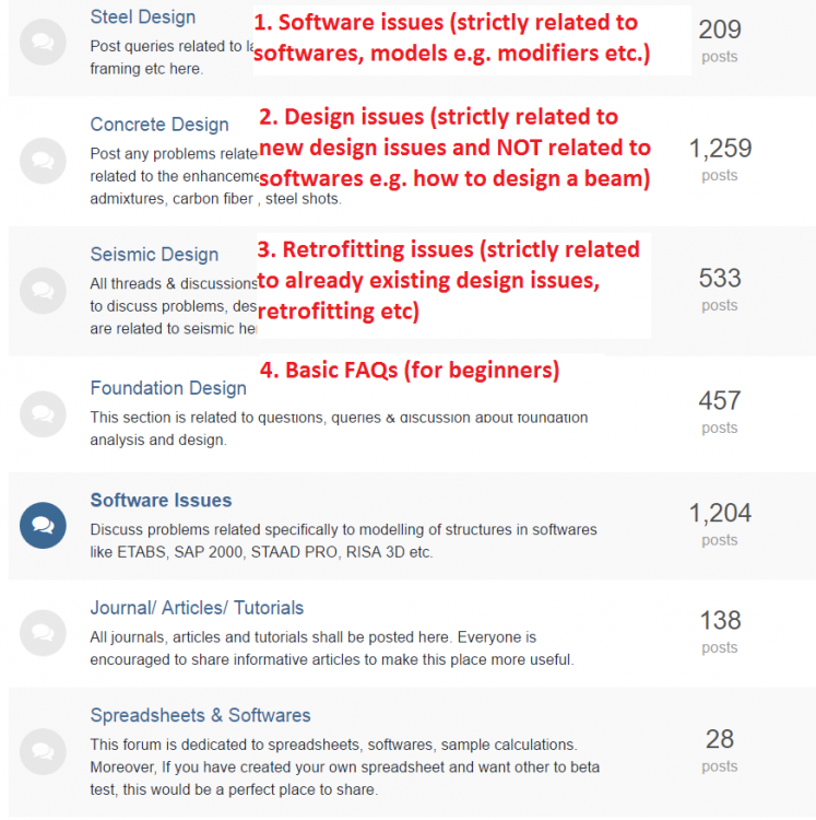
If a post is related to let's say wood design (and not to a specific software) we could ask the user to include tags such as "wood" in the question. I am opposed to making so many categories. That would create mess. We could control the sub categories by appropriate tags (strict policy to be imposed on users to input appropriate tags based on the materials /pre-defined sub-categories).
All users to be requested politely to contribute in the proper section. For example some one asking how to calculate the time period should directly go to BASIC FAQs section and search the thread, if not found then post the question. Or we could enforce new users to post only in the #4 section, unless we see that the user is not a university student but a more experienced one. So we, as moderator team, could grant him permissions to post in all the forum anywhere he/she likes.
This could be a bit more work for moderators but how many 'ACTIVE' users we have? Also this would keep the forum 'clean' and decluttered.
Don't you think each and every group on Linkedin and other places are full of one famous question about ETABS i.e. stiffness modifiers? Every new comer post the same question. And also don't you think following two questions should be in two different categories;
1. What is the purpose of stiffness modifiers in ETABS.
2. Although not required by ACI codes, how do you guys model the shear stiffness of shear walls? To reduce f12 or not?
etc.
Most of the times a design issue is always related to a specific software issue, such as no.1 . So the categories I have recommended are not the final words. Just a direction to start the discussion on the topic.
-
I think its time now to categorize questions based on the difficulty level.
For example;
A toddler asking very basic question like what is mass source or time period, should be classified under lets say Easy or 0 or Beginner or Simple etc category. And as such specific moderators should be assigned to take care of that forum.
Then we can make other sections like moderate or difficult. Where one really need to relearn/review the question and think about the answer carefully.
I think all the internet is full of the same basic questions like time period, base shear etc. Isnt it the time to take SEFP a step ahead and not just another forum full of the same basic questions? How can we re-categorize the SEFP sections to give it a new feel, not just like concrete, steel, software issues etc. What do you think?
- ILYAS, Waqas Haider, Fatima Khalid and 1 other
-
4
-
So what is the question?
-
By consistent, it means that in order to draw the ‘design’ response spectrum you got to know the PGA, PGV and PGD. Usually when these are unknown, PGA is taken as 1g. PGD and PGV are estimated by the relationships given by Newmark and Hall (see Chopra book). However, in your case, you already got PGV and PGD for PGA=1.0g, right? Now you have to make the pseudo-accelration/velocity/deformation spectrums based on this. After that, you have to scale the calculated response spectrums for 0.25g simply by multiplying them by 0.25. For more on this refer to Chopra book (4th edition) section 6.9.
-
22 hours ago, ShamiqSaeed said:
The only change I was making to the file was that I was changing the stiffness modifiers for the basement retaining wall from 0.01 to 0.0001,
That might have caused some inconsistencies in the calculations (very small/large values) and could have caused this error. There is not much diff in behaviour if you change from 0.01 to 0.0001 so keep the previous value.
5 hours ago, UmarMakhzumi said:That shouldn't cause any problem. Try uninstalling and reinstalling ETABS.
Thanks.
That would not solve the problem i reckon.
-
The biggest problem would be to control the excessive sway. The question you need to ask is if there would be any human occupancy in there/visiting deck etc? 99% chances are NO. There will be no human occupancy so limiting the sway & acceleration is out of the equation now. That leaves you with a sway limit of as high as 1/100 instead of usual 1/400 for buildings under service winds. You might need to pay attention to non structural components design for the drifts they gonna accommodate.
-
You question to me is unclear. Could you clarify what you wanna ask (may be in bullet points)?
-
Ask your self, why you dont check punching for the wall?
Think about the load it has, think about the area over which this load would be distributed (area bounded by the parameter equal to A+d). What value of shear stress you get? very low right?
-
@Hira Malik Your signatures stand out quite big. Mind making it in line with font size of rest of the posts?


Manual and Etabs result don't match
in Concrete Design
Posted
Please provide a sketch.