mhdhamood
-
Posts
157 -
Joined
-
Last visited
Content Type
Profiles
Forums
Events
Everything posted by mhdhamood
-
Maximum Allowed Steel Ratios In Slabs And Footings
mhdhamood replied to Waqas Haider's topic in Concrete Design
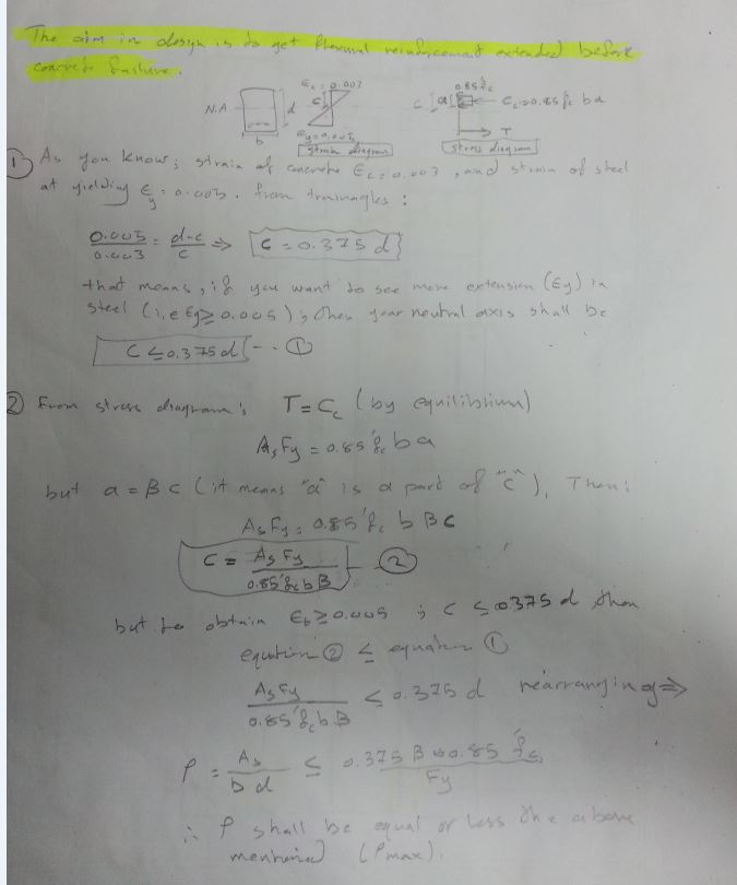
No dear, the maximum area of steel aims to limit the area of steel put in the section so as to control the strain in steel to be equal to or larger than 0.005. This will not differ between slabs and beams. Regards- 7 replies
-
- 1
-

-
- maximum reinforcement
- maximum steel ratio
- (and 2 more)
-
Mr baz; I know that you have mentioned. But what I need Sir is how from ETABS we can find if we have to increase the accidental torsion by Ax as UBC-code says, or not. Some one told me : 1. Go to Tables ...Result-----> Displacements -----> Story Max/average displacement -----> ratio values. 2. Those values are if >1.2 then we have to increase the accidental torsion as UBC-code says. please tell me if that okay or not. and if yes at any combination shall I work
-
Thanks all Mr baz ,Mr Umar and Mr Waseem
-
Dear Mr Umar; I have read but here I see a difference in the two articles ; Your article says that use for calculating seismic drift the ultimate load combinations from earthquake (three ones combine Dead+Live + spcx, spcy,spcxy and the other three that combines Dead+Spcx,Spcy,Spcxy) But Mr Waseem says that using only single load cases SPCX and SPCY.... which to follow ?? Regards
-
Maximum Allowed Steel Ratios In Slabs And Footings
mhdhamood replied to Waqas Haider's topic in Concrete Design
Dear Eng. Waqas for your question see the attachment Regards Mohammad
-
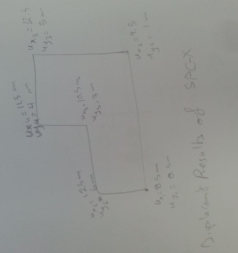
Dear All; Accedental torsion of the attached figure, how it can be determined . Please help?
-
NO members available?? Please help !!! and comment!!!
-
Aha I read Mr Waseem. But what I did here is Okay or not? Regards
-
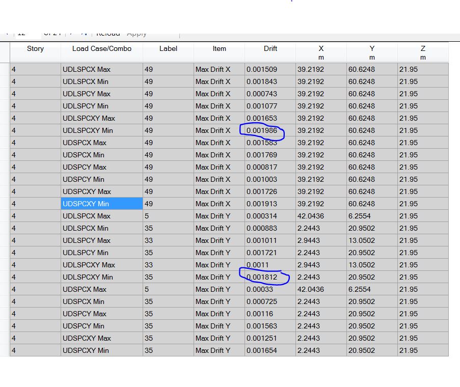
Dear all; I have prepared some procedures that in need to your evaluation according to your experience judgement. I am saying that the following procedures that I will mention will be trusted after your comments that agree or disagree. The procedure: 1. I get results from tables------> story drift as in pict.1. 2. Let us take one floor as a sample.For that floor we read the results of drift in x-direction as the maximum of all load combinations's results that contain earthquake i.e six load combinations as shown in pic.2 . 3. Do the above for y-direction. 4. As a result the for 4th floor; Drift-x = 0.001986 and Drift-y = 0.001812. 5. Now what are the values we get and how to use it. These values coming from ETABS are representing the difference in elastic displacement between the floor and the floor beneath or up divided by the floor height.(Please correct me if I am wrong). 6. Now to get the the seismic drift values from inelastic response we multiply the above drift by 0.7 *R . As an example let us say R=4.5 , then seismic drift-x =0.00625 and drift-y= 0.0057. 7. These values now are ready to compare with ACI code limitations, Assuming fundamental period of structure=0.5 second: story seismic drift limit =2.5% * story height 8. As you may see our story drifts either in x or in y are less than 2.5 %. Regards

-
The Width Of Design Strip For Single And Combined Footng
mhdhamood replied to mhdhamood's topic in Concrete Design
Aha Sir Umar; I consider that thank you so much you revealed a nice interpretation . I want to say for you and show my admire about you; that the knowledge grows when you spend from it . Regards -
The Width Of Design Strip For Single And Combined Footng
mhdhamood replied to mhdhamood's topic in Concrete Design
Thanks a lot dear .... -
The Width Of Design Strip For Single And Combined Footng
mhdhamood replied to mhdhamood's topic in Concrete Design
Dear Mr Umar; I attached a photo of what I mean. Please comment on that with all thanks to you . Regards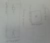
-
Dear ; I faced like that problem and I did the following: 1. I deleted the failed coupling beam from model so the forces will be transferred to the walls. 2. If the walls failed then you put other shear wall near to that failed , Regards
-
The Width Of Design Strip For Single And Combined Footng
mhdhamood replied to mhdhamood's topic in Concrete Design
Thank you so much Sir. Because we usually take the width of the strip to be the width of the single footing and the same for combined footing in the long direction. But for the short direction in combined footing we take for d/2 from face of supports. Just please tell me you do the same to share the experience. Regards -
Punching Shear In Safe Very Important Issue
mhdhamood replied to mhdhamood's topic in Concrete Design
Mr Umar Makhzumi; I would like to thank you to enter the discussion. Your discussion is appreciated. Regrads -
Punching Shear In Safe Very Important Issue
mhdhamood replied to mhdhamood's topic in Concrete Design
Dear, You have introduced a very nice discussion that reveal your excellent knowledge. Thank you so much. You made a big favor to me and I learned from you. Now I would like to say that I was wrong in: 1. I was very conservative in my estimations to perimeter of punching because I was ignoring the distance after d/2 when the edge is less than 4*h. 2. I thought that I have to recheck after SAFE program checks for columns near periphery. But I would like to mention that SAFE define the column according to 5*thickness of slab. Try to overwrite a column location type for a column having a free edge greater than 5*h( which should be treated as interior column) as edge column, then it will give NC (not calculated). Best Regards -
Punching Shear In Safe Very Important Issue
mhdhamood replied to mhdhamood's topic in Concrete Design
I have read dear. He says that this is applicable for also non prestressed. Also please read this for definition of columns : https://www.scribd.com/doc/36838507/Punching-Shear-ACI-Code
-
Punching Shear In Safe Very Important Issue
mhdhamood replied to mhdhamood's topic in Concrete Design
Thank you Mr Rana Waseem . I say about you you are like an ocean. You introduce a nice discussion. But let me say that : What is the definition of edge column ?. I guess from your paragraph that it is the one when you draw the perimeter which has three edges. But as this paper says http://docslide.us/d...aci-318-95.html. that the edge columns is the one has a free edge od less than 4* thickness of slab. -
Punching Shear In Safe Very Important Issue
mhdhamood replied to mhdhamood's topic in Concrete Design
Dears; Now its attached please note the pic
-
Punching Shear In Safe Very Important Issue
mhdhamood replied to mhdhamood's topic in Concrete Design
Dears; Please see the attached pic. I wish it is helpfull -
Punching Shear In Safe Very Important Issue
mhdhamood replied to mhdhamood's topic in Concrete Design
The problem how can I attach here ??? Itry to attach but the URL apperas... does that mean I need to upload this pic to a website?? -
Punching Shear In Safe Very Important Issue
mhdhamood replied to mhdhamood's topic in Concrete Design
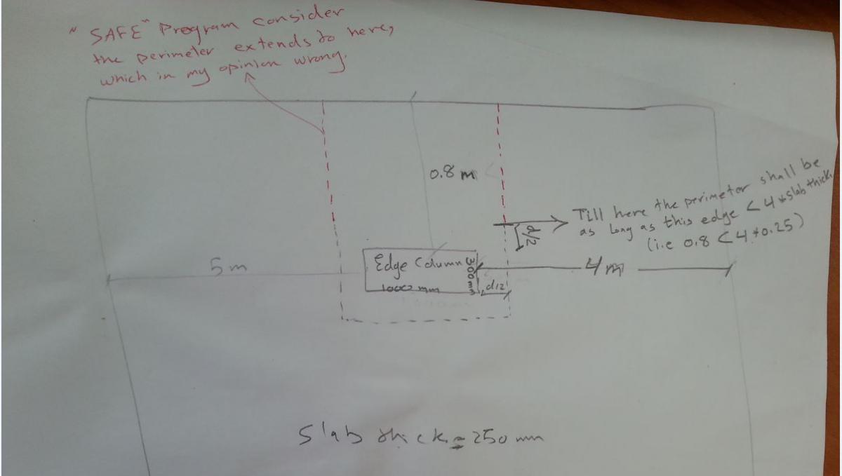
Dear Mr Rana waseem; Thank you. But I am not talking about what you attached. My case is that there is a distance behind an edge column less than 4*depth of slab( I mean not as perfect case which is =0 as you attached). Now this distance shall be taken only = d/2; not all the distance. This is shown in the following topic Figure3 b http://docslide.us/documents/design-for-punching-shear-strength-with-aci-318-95.html. Note that how that he didnt take the whole distance because it shall be ignored. Please if you all get my point tell me to proceed . Thank you all. Regards Mohammad -
The Width Of Design Strip For Single And Combined Footng
mhdhamood posted a topic in Concrete Design
Dear all; I want to ask in practical way about the width of design strip for single and combined footing; is it suitable to be 1 meter width or I shall take as the whole width of of the footing. Regards Mohammad -
You are right, some may take the remaining part of immediate delection(0.75* deflection due to live load) assuming 0.25 sustained load, adding it to long term def. the equation becomes : Long term Deflection = factor * sustained load + 0.75* immaediate due to live load Regards Mohammad
-
Punching Shear In Safe Very Important Issue
mhdhamood replied to mhdhamood's topic in Concrete Design
Dear Mr Rana Waseem; Thank you so much for your response. Exactly I am talking about a case like the following: 1. An edge column has a slab extent less than 4*(depth of slab) of one of it's sides; that mean it shall be taken as edge column and that direction will be ignored in calculations of parameter of punching except only for a distance of d/2 from that direction will be considered in computing punching perimeter. 2. As ACI papers; wherever the distance from the edge of column to the slab edge is less than 4*(depth of slab), that direction will be ignored in calculating perimeter of punching except for a distance of d/2. 3. The issue now that : SAFE program for the case mentioned in 1, will not ignore the slab for the direction where distance less than 4*(depth of slab). Other than it will take that distance in its calculations to the end of slab (Here is the issue, I mean it shall not take that direction because it is neglected as per ACI papers except for d/2 distance only........................ why is that? According to any code it works ??? Here to be sure I do the punching calculations manually but that time consuming). 4. The good news that SAFE will calculate another case of perimeter as an interior column for the above mentioned case, and takes the case with smallest perimeter.But still the issue why SAFE take the distance that shall be neglected into its calculations?. Your involvement is appreciated all. Regards Mohammad