
Badar (BAZ)
-
Posts
518 -
Joined
-
Last visited
-
Days Won
280
Content Type
Profiles
Forums
Events
Everything posted by Badar (BAZ)
-
Find out the first order moment (The moment without considering P-delta effect)as well as the moment by considering the P-delta effect.
- 4 replies
-
- 1
-

-
- column slenderness
- pdelta
- (and 1 more)
-
There is no restriction by ACI-318. Feasibility is limited to the imagination and practicality.
-
Yes, it is possible. The clear spacing between rebars should be as per guidelines of rebar-placement in columns. In order for rebars to transfer the tensile forces to concrete, they should have the development length with respect to the top of beam/slab on both sides, above and below.
-
I never use the default load combinations, I enter them manually.
-
This is a very loaded topic, it needs a lot of study. These are some of the documents: ASCE-41-13; FEMA P-58_Volume1_508 Seismic Performance assessment of buildings; PEER-ATC-72-1_Modelling and acceptance criteria for the seismic design of tall buildings; NIST GCR 10-917-5 Nonlinear Structural analysis for seismic design; NISTIR 7766 Evaluation of contemporary design of reinforced concrete. I am not aware of any tutorials on this one.
-
This parameter is used as a measure of torsional irregularity in the building. Building codes such as UBC 97 and ASCE7-10 have guidelines as to what constitutes a torsional irregularity. Buildings of all heights must be checked for this parameter.
-
I Can't figure out the question; Can't figure out the intent of the post.
-

Top and Bottom story range in STATIC LATERAL FORCE PROCEDURE
Badar (BAZ) replied to Fawad's topic in Seismic Design
I would say: get the demand in vertical members by considering this torsion.- 4 replies
-
- 1
-
-
- backstay effect
- basement
- (and 2 more)
-
It is preferable to adjust the framing in order to reduce the torsion. Having said that, the code does not restrict us to a particular value.
- 1 reply
-
- 1
-

-
- eccentricity
- torsion
- (and 1 more)
-
Depth of ETABS designed beam
Badar (BAZ) replied to Engr. Muhammad Salman's topic in Concrete Design
21 and 24 inches includes the slab thickness -
I also did not face this issue. While defining the load case, do you have the option of choosing the initial conditions of the load case for your version of ETABS? If yes, try playing with it to see if results change.
-
Check the initial conditions your load case. There might be issue there
-
Load Pattern, Load Combination and Load Cases
Badar (BAZ) replied to Engr. Muhammad Salman's topic in Concrete Design
When defining load cases, you have the option to select the type of analysis such as linear, nonlinear, static, response spectrum, time history etc.. When defining load patterns, the software only asks if it deal, live, earthquake etc. Use the option of Load combinations to superimpose effect of different types of load on your structural member. -
Colour coding gives the indication whether you section is safe or not. The upper limit should regarding the yield strength of rebar for as per ACI 21.2.2.4a, Table 21.2.2.4a of ACI 318-14.
-
Get hold of Seismic design manual and SEAOC Blue book.
-
Yes, you can. You can also design it for 2500-2700 psi and specify 3000 psi.
-
Wind loads will not govern if it is RCC structure, Seismic loads will be enough. 3000 psi is not difficult to achieve.
-
Structural System with small and economical crossection
Badar (BAZ) replied to Ahsan Kazmi's topic in Concrete Design
One Can't control drifts without adding RCC walls. Another option, impractical may be, to have RCC frame structure with reinforced masonry. -
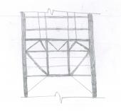
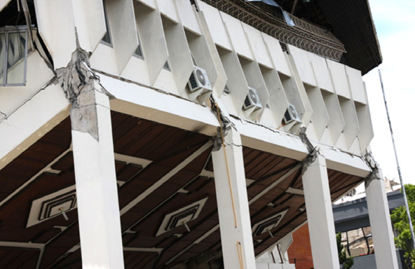
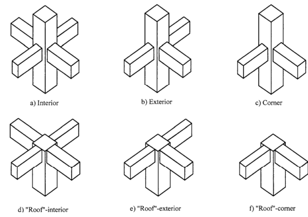
*SEFP Consistent Design**Pile Design**Doc No: 10-00-CD-0007**Date: April 16, 2018* 1.1. FUNCTION OF JOINT Beam-column joint must transfer the forces, such as moment, shear and torsion, transferred by the beam to the column so that the structure can maintain its integrity to carry loads for which it is designed. Another function of the beam-column joint is to help the structure to dissipate seismic forces so that it can behave in a ductile manner. 1.2.WHY DO WE CARE During an extreme seismic event, the code-based structure is expected to maintain its load-carrying capacity for gravity loads even after the structure deforms into inelastic range so that it does not pose any life safety hazard. Hence, the joint can go through significant degradation of strength and stiffness, and if it fails in shear, or anchorage, the life-safety objective of code cannot be achieved. 1.3.CONSEQUENCES OF FAILURE 1.4.THINGS TO CONSIDER FOR BEAM COLUMN JOINT Longitudinal bars of beams, or slab, must be able to develop their yield stress, so that the beam/slab can transfer moment to joint. It means that longitudinal bars must have adequate development length for hooked bars. This implies that the size of the column must be such that bars can develop their tensile forces. If bars can transfer moment, they can also transfer shear as far as monolithic construction is concerned. The shear strength of the joint must enable the transfer of moment and shear through it. The joint should be Constructible: Congestion of reinforcement is the main concern. 1.5.DESIGN SHEAR FOR BEAM COLUMN JOINT The design shear for beam-column joint depends upon the relative strength of beam and column at the joint. For the joints part of the special moment resisting frame, the shear force will be the one that corresponds to the development of hinge in the beam because the frame is required to satisfy strong column-weak beam criteria. If it is a knee joint, then joint area must resist the shear equal to the development of tensile force in the beam. The tensile force will be equal to the product of the area of tension steel, yield strength and the factor that represents the overstrength of steel rebar. If it is not a knee-beam-column joint then, the design shear of the joint will be algebraic sum of tensile force in the beam and the column shear. The column shear is the one that is required to keep the joint in equilibrium, i.e the shear corresponding to the development of the probable moment capacity of beams at the joint. For the joints not part of the special moment resisting frames, one needs to investigate whether the beam or column will yield first. For knee joint, if the column is weaker then the beam, the tensile force cannot exceed the moment corresponding to the development of hinge in column 1.6.THE JOINT: Definition and classification Portion of column within deepest beam that frames in to the column (ACI 352-02). ACI 352-02 categorizes joints based on the displacement-demand imposed by connected members. · TYPE 1 (Section 2.1.1 ACI 352-02) These joints possess limited ductility, and hence the connected members are designed for limited ductility. They are used in situations where ductility of structure is not a concern. · TYPE 2 (Section 2.1.2 ACI 352-02) These joints connect members which designed to have sustained strength under large deformations. Joints are also classified based on their location in framing system 1.7.THE JOINT: Design forces The joint is designed for the shear that results from attainment of the flexural strengths of members connected at the joint for type 2 joints. For type 1 joints, same principle is employed, unless the both members are overdesigned and the engineer does not expect both members, i.e. beam and column, to yield under design forces. 1.7.1. FLEXURAL STREGNTHS: TYPE 2 No strength reduction factor is used for computation of flexural strength. Steel stress is multiplied by factor of 1.25 for computation of flexural strength (3.3.4 ACI 352-02). For type 2 joints, the flexural strength of beams needs to be calculated only, as we do not expect the hinge-formation in columns; we will proportion the beam-column assembly of this joint as per strong-column-weak-beam approach. The slab reinforcement within the flange of beam must also be considered for computation of flexural strength of beam if the slab is integrally cast with beam and if the longitudinal reinforcement of slab is anchored (3.3.2 ACI 352-02). For interior connections, and for exterior and corner connections with transverse beams, the portion of slab to be considered as flange should be as per guidelines of section 6.3.2 of ACI 318-14. The effective flange width should not be taken less than 2 times the width of beam. For exterior and corner connections, without transverse beams, the effective flange width should be as per figures below (section 3.3.2 of ACI 352-02). The effective flange width for this case need not be taken more than 1/12th of the span of the beam. 1.7.2. FLEXURAL STREGNTHS: TYPE 1 For type 1 connection, similar procedure as discussed above should be used, if beams are expected to yield before columns. The stress multiplier factor for this type of connection can be taken as 1. The beam reinforcement, if any, as per section 24.3.4 of 318-14, with-in the effective flange width, must be included in determination of flexural strength in addition to the web reinforcement. If columns are expected to yield before beams, the nominal flexural capacity at beam-column joint should be calculated with due consideration given to the axial load on column. The beam moment in that case would be the one required to maintain equilibrium of the connection. If neither the beam, nor column, is expected to yield at factored loads, then the design shear of joint would be based on factored forces, moments and shear, at beam-column interface.
- 4 replies
-
- 5
-
-
-
- beam-column joint
- sefp consistent design
- (and 1 more)
-
I missed the post as well.
-
In most cases, the force in the collector is not enough to enforce enlarged-section in the form of a beam. The reinforcement can be provided within the slab. There is no other way, One has to complete the load path.
- 2 replies
-
- 1
-
-
- collectors
- seismic
- (and 1 more)
-
It is not only the difference of moments, the difference of axial load is also responsible for increased demand. The lower axial load, coupled with increased moments is the reason. In top story, the unbalanced moment is distributed among three members. In lower stories, four members share the unbalanced moment at the beam-column joint.
-
If you will follow detailing of ACI then the foundation will provide rotational restraint. Modeling it with the pin is under-conservative. Column's longitudinal reinforcement is a function of the size of the cross-section, material strengths, axial force and bending moments. Compare them.
-
Look at the design forces of members and compare, you will get the answer. Why are you modeling the foundation as the pin?
-
You will assignment diaphragm property to your joints when you are not modeling area elements ( shells, plates or membrane) in the model, but the joints are connected by a horizontal area-member, or some combination of line-members, that will act as a diaphragm in the actual structure. ETABS will use it to distribute lateral forces to all joints based on that diaphragm property.