Search the Community
Showing results for tags 'shell interpretation'.
Found 6 results
-
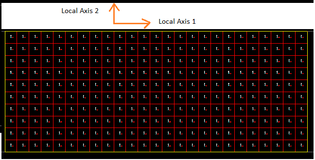
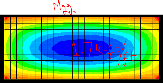
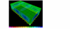
Hi everyone, I have been analyzing a singly story frame slab supported on four beams in SAP and Etabs. However, I am getting greater moments in longer direction than in shorter direction. Please see the attached figures highlighting the local axis as well as moments in both short and longer direction. I am always getting greater moments in longer direction than shorter direction whether I analyze a two-way slab or one-way (I get moments larger moments in longer direction which is not the case I know). Feedback is requested. Thank you

-
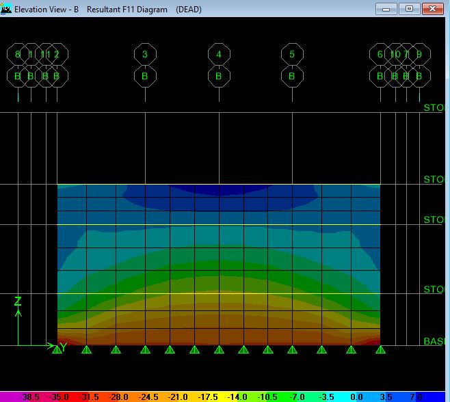
HI . i Do analyze shell element ( vertical wall ) and found its result as this . for dead load when i see F11 it show me below diagram with some valve positive and some negative. what that positive and negative means ? is that tension and compression ? if yes so what sign used for compression and what for tension ?
-
Dear anyone, I am designing a dome with radius 40'. I have designed it manually (i.e amount of meridian and hoop stresses ) but since the dimension is very large, i have difficulty in designing the circular beam under dome (their occurs very large bending moment). i had searched the forum but every attachment has been either removed or is no longer available. now i am trying to model and design it in Etabs. and i read the material on forum the method using extrude properties command, but what properties should be assigned and what results should i be looking for?
-
Attached is a thin plate stress distribution done in SAP2000.The units are KN-m.E value is 210GPA ,and the area section so choosen is shell thin with plate thickness t=20 mm, the thin plate is idealized into two triangular element with a 'None' element to connect two area elements at the diagonals. Along x axis is 400 mm and y axis is 200 mm.The manual calculation matches exactly for the displacement at nodes.However,the shell stress is not matching .As per manual calculation ,the sigma x and sigma z are coming out to be 6964.53 KPa and -7.53 KPa respectively. However in Sap2000, sigma x or S11 is about 6859.44 Kpa,while S22 is about 990.34 KPa and S12 or Txz is about -97 KPa from the calculation whereas from manual calculation it is -16.1 KPa???why is it that ,is it because it is not meshed or so? Please spread some lights on shell stress and my understanding on it .I have attached here the stress contours and displacements. stress.docx
-
 Hi, I am designing a load bearing masonry wall in ETABS and using IS 1905 code. After viewing the shell forces and stresses, I know that I need to use M11 forces for the design of lintel/horizontal bands to take out of plane lateral loading. But in ETABS i found that the forces are displayed in a unit of KN-m/m (per unit length). How do i convert this value to the total moment for the design of the band. Do I multiply this value by the shell meshing length? Please educate. Structural Engineer Nepal
 -
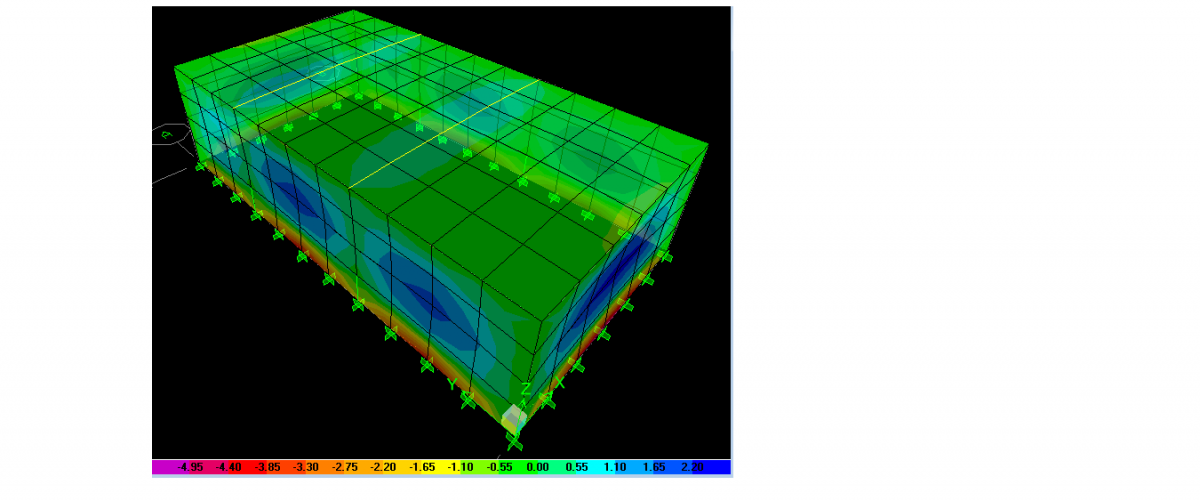
Assalam o alaikum, In Etabs, How to interperate Shell stresses/Forces. I highlighted M22 Force and i got max value as 2.61 in kip-ft units and minimum as -5.112 in Kip-ft units. What i found from the link http://docs.csiamerica.com/help-files/etabs/Menus/Display/Show_Member_Force_and_Stress_Diagrams/Shell_Forces_Stresses_Form.htm that M22: Direct moment per unit length acting at the mid-surface of the element on the positive and negative 2 faces about the 1-axis. Does it mean -5.112 Kip-ft/ft and is M22 the moment for which i am to calculate vertical steel. Kindly suggest me the value of Mu for which i am to design reinforcement. I have also attached Picture.
- 6 replies
-
- 1
-

-
- shell
- shell stresses
- (and 2 more)


.thumb.jpg.700916fbc7ead330085e15745d0270bd.jpg)