

UmarMakhzumi
-
Posts
1,471 -
Joined
-
Last visited
-
Days Won
447
Content Type
Profiles
Forums
Events
Everything posted by UmarMakhzumi
-

Concrete wall with pointloads and distributed load
UmarMakhzumi replied to Injective's topic in General Discussion
Injective, You can find the resultant of all applied loads and distribute that reaction as liner load along length of wall.. Take moment at any corner and find the resultant. Thanks. -
That would help as soil has some limited elastic behaviour and can be idealized as springs. Here is a related thread that might be useful. Thanks.
-
Please see the following:
-
Steel Plate design using Euro Codes (UK National Annex)
UmarMakhzumi replied to Asif's topic in Steel Design
Hi Asif, Why don't you do a FEA analysis in any standard software and compare the peak stress with the max allowed by the code? Thanks. -
Footing design on Equivalent Static or Response Spectrum case?
UmarMakhzumi replied to Eng.Hasnain's topic in Seismic Design
Regarding signs, they are lost in RSA, but your load combinations should cover this as you will design for +E. -E in each direction so that's fine. What you do per code is the minimum requirement but often times checkers might ask you to do other checks, which can be based on their judgement. People mostly comply. Thanks. -
@waqar saleem, please share your mass participation tables similar to what Sir Zeeshan has done above. Not everyone has access to ETABS. Thanks.
-
I wouldn't suggest Box Girder type as it will reduce your bearing area. Also, for foundations, one pour is always cheaper. If you want to reduce thickness then you might re-look at framing (adding more columns/ walls) to avoid areas of high concentration of forces. Thanks.
-
Need a little Guidance of Software for Foundation Design
UmarMakhzumi replied to Jawwad Khalid's topic in Member Introduction
Waqar has a valid point but since you are also an engineer, you can start with manual design (review course notes) and for foundation software, CSI SAFE is widely used in Pakistan for foundation design. Thanks. -
ETABS Design Not showing any Steel for Beams and Slabs
UmarMakhzumi replied to Sharjeel_ghauri's topic in Concrete Design
It is hard to tell, especially when I don't have time to review your Model. All I can suggest is going through the Basic Loads check and re-checking your input. Also, is your copy of ETABS licensed or not? If it is not licensed, then the version you are using might be buggy. Thanks. -
Hi @Rahulkld, That is expected. Since your bottom and top chords have high axial load near support, the first 2 diagonals are always critical. You can use heavier sections for the first two diagonals and lighter elsewhere. Thanks.
-
ETABS Design Not showing any Steel for Beams and Slabs
UmarMakhzumi replied to Sharjeel_ghauri's topic in Concrete Design
It can be due to a number of reasons. If your 3 storey building design was reasonable and this one is off, you could have made a mistake in applying the loads (check units), defining material properties (again check units) or load combinations. Check your reactions for basic load cases and manually do and compare controlling load combination reactions with ETABS. That would be the starting point. Thanks. -
I think @Simple Structures has UK experience and would be able to help. Please reach out to him. Thanks.
-
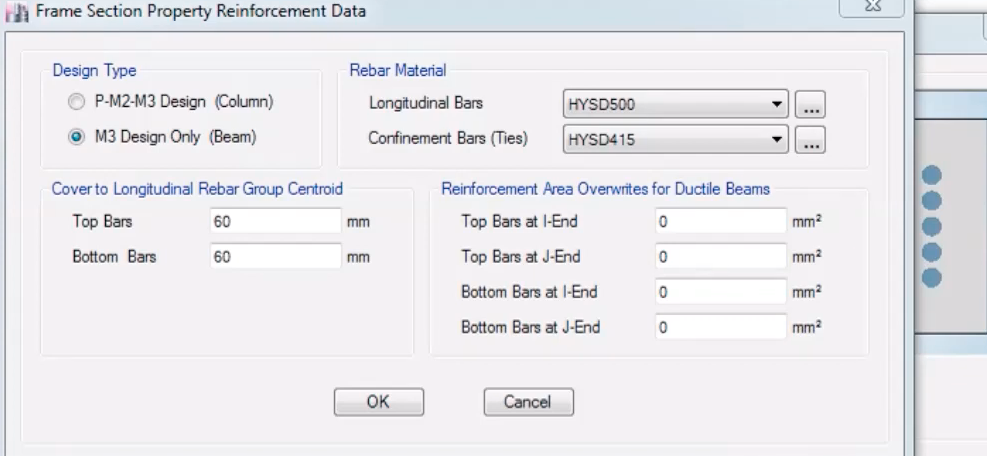
Rifat, I think you can define it in Frame Section Property Reinforcement Data. If your question is about cases where reinforcement is not defined, I don't have the answer on hand as I am out of ETABS for 10+ years now. Thanks.
-
Walikum Asalam Rifat, This might help: Thanks.
-
Isolated footing desgin / Porch Column
UmarMakhzumi replied to Muhammad Usama's topic in Foundation Design
Hi Usama, There are a number of ways load development can be done. If your wall are self supporting, then you don't need to transfer any loads from walls to the column. The column can be designed as independent member taking loads from porch. However, if your wall is anchored to the column, it may transfer wind load to the column and seismic loading, depending on the connection between wall and column and if that is the case, you will need to account that force in your column design. Hope this reply helps. Thank you. -
Etabs analysis - Effect of shell mesh on results.
UmarMakhzumi replied to Alexcy's topic in Software Issues
Interesting results. Hard to tell what’s going on in there. -
If there are no secondary beams and there the slab is pure concrete slab, you can use shell elements. just make sure your boundary conditions represent the connection you select with steel. You can use Nelson studs. They transfer shear only with limited tension so you need to model the slab boundary conditions accordingly. Thanks.
-
Please read Waqas Haider above post 👆 Thanks.
-
The allowable settlement criteria is based on utility of structure. For examples, in Process and Oil & Gas industry, piles supporting structures that have pipes are normally limited to 6mm vertical deflection. This value of 6mm is also considered by Pipe Stress engineering when they are doing their pipe design and in this way the design comes to full circle. Differential settlement is also considered. If you are asking for a building, the it depends on what values your building columns can tolerate considering differential settlement and not fail. Piles undergo short term and long term settlement in clay soils. You should evaluate both based on the recommendations of geotechnical engineer and see how the values affect your superstructure. Thanks.
- 1 reply
-
- 1
-

-
You need to change configuration / framing layout of your structure to change the mode and their participation. Thanks.
-
Baz replies are very detailed, and here is one item I can re-elaborate on since you have asked it again. Because the way your slabs are being connected to your beam (The slab is connected to the face of the beam), you will always have torsion and you need to deign for that torsion as that is the only load path from slab to beam with the provided connection concept. If you want to reduce or avoid torsion, your slab to beam connection philosophy needs to be revised. For example, if this hollow slab was "casted above the beam" you will not have this issue (torsion will reduce at the center beams but will still have torsion at corner beams), but you will need to connect your slab and beam through some system and in that way your beam depth will be much smaller. Thanks.
-
-
Excellent answer by @Badar (BAZ) like always. I will add to the last item posted that you can do quick plate analysis and get max moments. If you choose to proceed this way, after get your analysis results, please add you Mx and Mxy together and design the slab for this total moment. Thanks.
-
Hi Leong Shi Ming, The easiest way is to look at your "Joint Displacements" and hone down on joints where displacements is very very big. Also, checking displaced / deformation shape helps. Hope that helps. Thanks.
-
Thank you for sharing this Uzair Sb!!.
