

UmarMakhzumi
-
Posts
1471 -
Joined
-
Last visited
-
Days Won
447
Content Type
Profiles
Forums
Events
Everything posted by UmarMakhzumi
-
Dear Zeeshan, You can model this in ETABS or SAP using Shell Elements or Line elements. I am not familiar with CSI Bridge. Regards,
-
 It should be. The B2 Bar X Dimension should be long enough to develop so that fixed end connection can be satisfied. I am not sure what assumptions they had for the design. Do you have any way to get intouch with them and clarify this? Thanks.
 -
Is the Barrel Section a vertical section or a horizontal section? Looks more like a horizontal section to me, but I could be wrong as not familiar with these. A1 bar is for +ve moment (Sag, where tension is at the bottom) and likely the location of moment would be in the center (assuming) so you don't need to develop it with hooks as not required and rebar is developed at critical section. The dowels from the wall are protruding even if the wall is casted first. The dowels go in slab and will be covered by slab concrete. If there is no force reversal, you only need to develop the negative rebar for gravity loads to consider the wall-slab join as fixed which they have. Thanks.
-
Hello Everyone, I got an email from a new member that he was facing problems with the validation email that is sent when a new account is created. I have manually approved a few members but I am looking for feedback. If other member have faced the same issue, please let me know. Thanks.
-
Hali, The above reply is excellent. To make things more lucid, I will add the following to above answer. Correct. There are different ways. Certain Codes allow low/ non-seismic applications to reduce development length by As provided\ As required ratio (including ACI). Other options include mechanical anchors, assuming pin condition in analysis like Baz mentioned above and increasing the size of members. Ldh is length up to hook. Don't add 12*Db. Haha. You are doing great. These are good signs. Here is tip. If you already don't have, get a copy of PCA Notes on ACI, and see examples in that document. It will clear up any ambiguity that you have and also it serves as good reference. Thanks.
- 12 replies
-
- 2
-

-

-
- hooks
- reinforcement detailing
- (and 1 more)
-
Your case is tricky. Your shear walls will still resist load but differently. To see that happening, you will need to model the stair slab (diagonal & Landing). Also please see this thread: Thanks.
-
Depth will help for the case of moment frame. Width can have a very minor to negligible effect as contribution of beam width to moment of inertia is small.
- 7 replies
-
- 2
-
-
- story drift
- drift
- (and 1 more)
-
Yes, I think you are right. Should be less moments in the middle and more at the end. (to be clear) PCA has a publication where coefficients are provided for 2 way slab bending based on boundary conditions. I believe it was also posted in the forum some time back. You can use that. Thanks.
-
Strong column, weak beam. @Badar (BAZ) is our expert on this topic. I believe he can shed some light on beam column ratio etc.
- 2 replies
-
- 1
-
-
- beam column capacity ratio
- asce 7-10
- (and 1 more)
-
Thank you for updating on this. If someone else gets into the same issue in the future, your post would be of great help to them.
-
Interesting. Thanks for sharing.
-
Azshah, Reinforcement to be checked should be used when you "Define" the column reinforcement and provide the steel which you plan to provide on drawings. Normally this option is used when you are checking existing brown field structure where reinforcement is known. When you want ETABS to design the reinforcement (tell you how much is required), you go with reinforcement to be designed and provide that reinforcement. Thanks.
-
W.salaam, My suggestion would be that you still use the minimum specified yield strength of 460 MPa, as you are testing limited number of bars out of of thousands of bars that will be used for the structure. Also, it is good to keep some contingency as there are a lot of assumptions and limitations involved. Thanks.
-
Structural Dynamics and Earthquake design lectures
UmarMakhzumi replied to Omer Ahmed's topic in General Discussion
Clean website and useful information. Thanks for sharing.- 1 reply
-
- 1
-
-
There is one tutorial on CSI Wiki for SAP2000. You can see if the same feature is in ETABS. I can't check as I don't have ETABS copy with me. https://wiki.csiamerica.com/display/tutorials/Radial+point+load Please download the attachment, report.pdf and read it. Thanks.
-
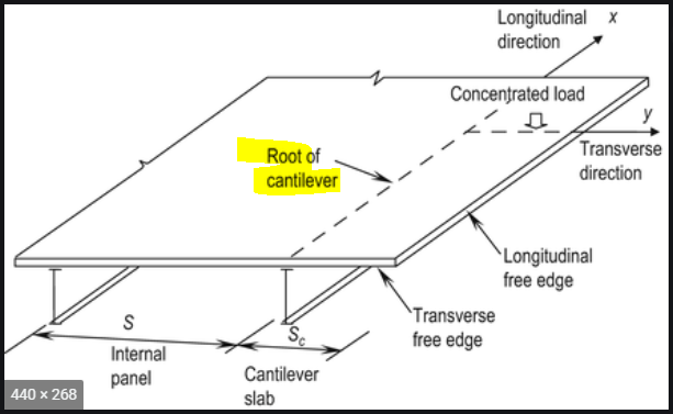
Backspan is there as it needs to meet development requirement. That is the only purpose. What Baz is referring to is the Stability Requirements at Cantilever root (see snapshot below for understanding). What that means is that your beam at location where it is supported on the wall should have lateral stability (either other beams coming from the side frame into your cantilever beam, or something stopping your cantilever beam from twisting). These requirements are well understood in steel design. I am attached a document that can provide you some insight from steel point of view. You can take that understanding related to stability and apply to concrete. Thanks. Cantilever Beams_Steel.pdf
-
Welcome to the forum Kaleemo. Glad to have you on board. Thanks.
-
Vertical springs stiffness is obtained by dividing the load on pile by its deflection. Geotechnical provides recommendation on how to calculate pile deflection. The above post by @ILYAS is about horizontal pile spring. The area is the side area (Pile dia * height b/w spring) not the cross-section area.
-
Hashmi, For steel piles that are hammered/ driven in the ground: 2.5 * Outer Diameter of the pile is the minimum distance that is kept in Canada (I think this comes from Canadian Foundation Engineering Manual but can't recall the reference). This is out general accepted practice but normally we want to keep the minimum distance as 3.0* Outer dia of pile. If that can't be achieved then we go for 2.5*D but never lower than that. Sometimes, the piles will heave a little out of ground when adjacent piles are being driven (even with keeping 2.5-3 *D) distance. Such piles should be re-tapped. Thank you.
-
Hashmi, I am not sure if I get the question right, but can you please check this thread and post any follow up. I think what you are asking is answered there. Please let me know. Thank you.
-
Isolated foundation design for container house.
UmarMakhzumi replied to tahir younas's topic in Foundation Design
I can answer any question posted here. -
The general practice in a lot of design firm in Pakistan is to design the shear walls with 100% of base shear even if you you opt for dual system and to design the frame for at-least 25% or more.
-
W.Salaam, There is a lot of recent posts on the forum about designing masonry in ETBAS/Safe. I would suggest you to search the forum to get the required answer. However, please note that we don't recommend using ETABS for Masonry design as it is a frame analysis software. You should either try locating a masonry design software or buy a masonry text book and follow the examples. Regards,
- 1 reply
-
- 1
-
-
Isolated foundation design for container house.
UmarMakhzumi replied to tahir younas's topic in Foundation Design
Tahir, I do hope you can find someone that can walk you though. The important thing would be to design for wind and the connection of container to your foundation. -
Hello, I came across this video yesterday. This is very useful if you are new to investing.