

WR1
-
Posts
985 -
Joined
-
Last visited
-
Days Won
286
Content Type
Profiles
Forums
Events
Everything posted by WR1
-
This is a quick check handy formula. Look for "buildings of moderate size and height" book. But that does not prevent you from going on checking in more detail.
-
Refer to any structural design book. To me, this thickness would be safe; req thk = 10 (700*4.448)^0.5 in mm
-
1. Import the original text file again. 2. If it doesnt work, assuming you have lateral loads, goto Tables > and show reactions for Ex, Ey ..etc...once the reactions are tabulated. Close and then try again printing the summary report from File menu.
-
First; minimum reinforcement (temp/shrinkage) reinforcement could be divided in half, for top and bottom. But in case of footing of such a huge size, i believe you are already providing more than minimum reinforcement at bottom, so at top you should provide full Asmin. Second; you do not need to consider the full 6' depth of base slab minimum reinforcement. Its a mass concrete. The exact reference slipped out of my mind. I will update if i come across the clause. But meanwhile may be you can dig a little more on google etc.
-
Yes, when you export to SAFE, columns will be fixed. You can do following; 1. In SAFE, change the fixation to springs, iterating several times for spring stiffness, until you get the same deflection under each column matching with those in ETABS. Quite cumbersome (almost impossible). Also the SAFE deflections you would be comparing with those in ETABS are not compatible. In ETABS you modified the stiffness by assuming modifiers while in SAFE, the cracked inertia analysis is done based on section and reinforcement and moments. 2. So, the other option is to design it inside the ETABS. I guess in ETABS 2016 you can design slabs as well.
-
Yes if you keep k=constant. That means for a given stiffness of a structure, higher mass would give higher T because the lower stiffness is unable to hold back the higher mass. Example: Tall buildings I guess you are working with long period seismic waves on tall buildings? If so I have done masters thesis on the same topic. Not sure what you gonna achieve but here is an excerpt from my thesis; Response of a building to ground displacement, velocity or acceleration depends on the time period of the building. For example, the response of a tall building (time period of more than 3 seconds) will be more sensitive to ground displacement as compared to ground acceleration and velocity and is recognized in some building codes; for example in Japan (Fédération internationale du béton, 2003, p. 94). Excerpt from the thesis; A rigid structure will vibrate as it is a part of the ground itself. A rigid building will move with the base; however the upper portions of a tall building do not move with the base due to the resistance of inertia of masses, and bend in many complex modes (Taranath, 2010, p. 348). The mass at top floors remain stationary while the base of structure moves with the ground (Taranath, 2010, p. 379). So the response of the structure and the input acceleration loads are lagged. It takes time for the shear forces to accelerate upper masses in a tall building depending on the stiffness and mass of storeys (Carr, 1994) as is shown in following figures. I have attached the relevant pages in this post. If you are working on the same topic I can share with you the whole thesis. Good luck. Chapter-3.pdf
-
You can take directly the model quantities from ETABS itself.
-
Why would you like to stick to static analysis? Perform the simple dynamic analysis using MRSA. Why use UBC when you can use ASCE (Dynamic base shear=85% of static as opposed to 100% in UBC for irregular structures). You save a lot here! Why not use some exciting concepts like scaling base shear to static base shear based on Ta if T-dynamic < Ta. Why not use a rigid diaphragm instead of a semi-rigid one. Try using 0% live load in seismic mass if it is not a ware-house/permanent storage. Try using weight/mass modifiers for beam (beam-slab over-lap) to reduce the overwall W. Think how can u reduce W even further.
-
Your system most probably gonna fall under 'building frame system' = lateral from walls + gravity from frame Remember that, mere presence of frame with walls does not make the system as dual system or whatever...inertia of columns is usually so small to that of walls. A building could have very few walls and many columns but still the columns resist 0% of lateral loads. It depends on relative stiffness. Run the analysis as is wit any R factor, check the horizontal reactions for walls and columns. See how much percent they resist. You would notice in such type of structures that lateral resistance by walls is around 70% and rest is from columns. Check these numbers. If it is walls=100% and cols=0% for lateral and opposite for gravity, its an ideal building frame system. If however columns also resist 'few percentage' (see SEAOC) of lateral and walls resist 'few percentage' of gravity then there is an additional task to perform to make sure it is still a building frame system. Conceptually you have to make sure that, during an earthquake if walls are resisting portion of gravity load, they should possess this capacity (do not lose load carrying capacity during an earthquake). If so the framing is still a building frame system.
-
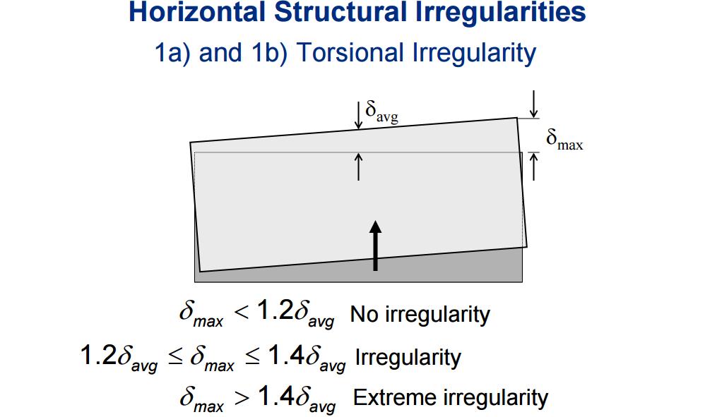
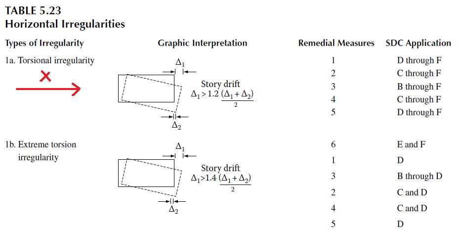
Yes you are right. If loading direction is X, check x displacements on point 1 and 2 on the edge that is perpendicular to loading direction. Following will clarify; 1. Load in Y Direction Source: FEMA; https://c.ymcdn.com/sites/www.nibs.org/resource/resmgr/BSSC/Topic09-SeismicLoadAnalysis.pdf and 2. Load in X direction: Source: Reinforced Concrete Design by Tranath
- 3 replies
-
- 2
-

-
- torsional irregularity
- table 16-m
- (and 2 more)
-
1. Your observation is correct that Sin(6.8) on calculator = sin(radians(6.8) provided your calculator is set in degree units. What you have used in Excel formulas [ sin(radians(6.8) ] is correct if; the angle 6.8 originally was in degrees. Was it in degrees? See the formulas you have attached in Excel. I do not think so. Why? Because circular frequency (w) is usually is rad/s. So your units are already in rad and you do not need convert them further and Excel is already set in rad units so just use directly the sin(6.8). This is what @Saad Pervez pointed out.
- 4 replies
-
- 2
-
-
- structural dynamics
- akchopra
- (and 1 more)
-
Avoid it. Totally avoid it. Just put the expansion joints.
-
Yes it looks okay.
-
Applying triangular load on plates/shells in ETABS or SAP200
WR1 replied to groszni awesome's topic in Software Issues
That is a common FEA problem. You get infinite stress at supports due to infinite stiffness.This is a problem of stress concentration. For commercial design purposes what you did is okay.- 9 replies
-
- 1
-
-
- triangular load on plates
- triangular load on shells
- (and 1 more)
-
1. You need to divide the buildings to avoid irregularities especially in zone 4. 2. start with a crude model, no shear wall (only columns) and try to get the general feel of the structure. For that you could also roughly estimate the gravity loads (for mass source). For example 15-20 kpa let say (including sw+sdl+ll) as gravity load. 3. Iterate by putting in shear walls where you need it. Once the crude geometry is finalized you can go for detailed modelling/design and you will find out the importance of concept stage design at early stage.
-
Suarez, we do not handle pirated/cracked stuff. Please be aware in future.
- 1 reply
-
- 1
-
-
Solutions; 1. Why dont you import the cad drawing (as shown in image) into SAFE and draw footings with proper orientation? 2. Like you got reactions under so many combinations from ETABS for each column, in the same way, you could select all columns and export to EXCEL the local forces at and then filter for zero location and proceed with manual design. 3. Get global reactions (like you did already) but one group at a time. By one group i mean all the columns on one radial grid line. All columns on that grid will have same orientation and angle right. Export to EXCEL, transform forces in XY to that angle. New rotated forces will be; Fx' = Fx Cos theta + Fy Sin theta Fy' = -Fx Sin theta + Fy Cos theta there you go, you now have the new rotated forces. Repeat it for each radial line and then design footings manually.
-
reinforced concrete longitudinal rebar placement
WR1 replied to groszni awesome's topic in Concrete Design
Depends on design moment combination. Thats why i always recommend putting in the right reinforcement in columns in ETABS and put it on 'check' instead of design.- 3 replies
-
- 1
-
-
- moment
- reinforced
- (and 2 more)
-
It might be this; "For concrete frame design using the ACI 318-08 and ACI 318-11 codes, the design report for "Shear Details" has been enhanced for "Sway Special" frames by adding the field Design Shear (Vu) for clarity. Previously, only the factored Vu was reported, which may not be the governing force for capacity design." Incident Id: 64173 in ETABS 2013 13.1.4 enhancement user notes.
-
It could be. For example if you are checking shear at ground floor pier, it could be more than the shear force of floor diaphragm. This is due to the additive effects of upper stories. Meaning, shear in that pier will be the shear from floor diaphragm plus any residual shear force coming from upper stories, depending on shear force diagram. Yes, values will be either positive or negative. Is there any third possible sign? Secondly, you did not mention the results coming from static analysis or dynamic analysis? Remember that equilibrium from linear dynamic analysis such as MRSA are not possible.
-
It looks like newer version of ETABS. Vu for frame or wall? I am sure there must be something written about Vu* in ETABS manual/help.
-
Applying triangular load on plates/shells in ETABS or SAP200
WR1 replied to groszni awesome's topic in Software Issues
Yes or by any other mean like manually applying the joint loads. -
Applying triangular load on plates/shells in ETABS or SAP200
WR1 replied to groszni awesome's topic in Software Issues
You can do like this; What you have to do is to note down the z coordinate of each shell element along the height (in Excel e.g.) and calculate the force at top and bottom node of each element, then apply the average pressure in local axis 3 (plus or minus). Tip: Always model retaining walls/swimming pool etc so that all the walls have local 3 axis either inside the pool/container or outside. So you can select all the walls once and apply the pressure in one go. And for that turn on 3d view in XZ or YZ in ETABS and select top most mesh, apply pressure and so on. Its not that difficult. To calculate average pressure you can either make your own excel sheet or use the following I once made. Water Pressure on Walls in ETABS.xlsx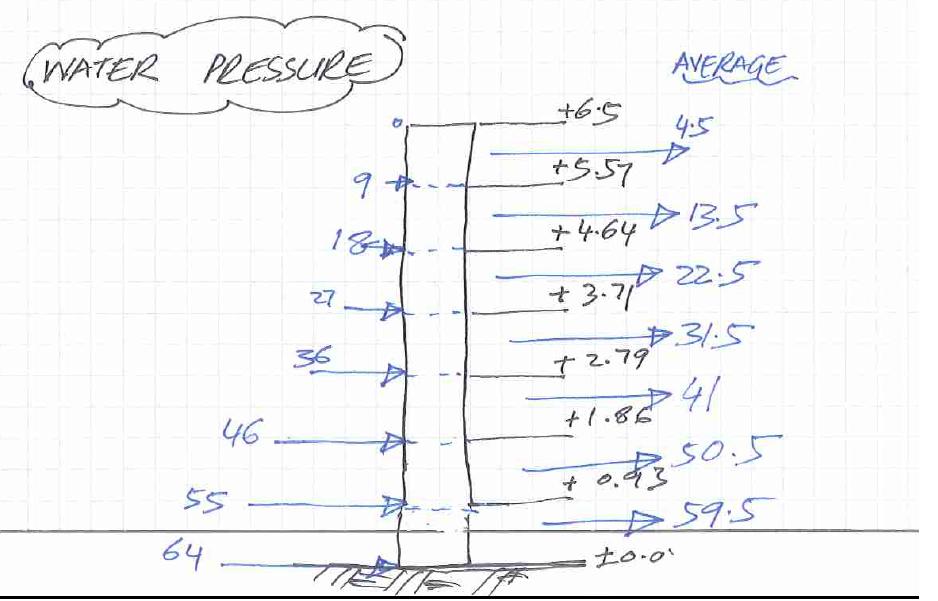
- 9 replies
-
- 5
-
-
- triangular load on plates
- triangular load on shells
- (and 1 more)
-
Not sure about Pakistan building code, but this might be of your interest; http://www.concrete.org.uk/fingertips-nuggets.asp?cmd=display&id=750 Or in ACI 365.1R http://civilwares.free.fr/ACI/MCP04/3651r_00.pdf Or in terms of sustainability as per BRE (Building Research Establishment) or BREEAM program http://www.gov.scot/resource/doc/217736/0091011.pdf Also see this http://www.structuremag.org/?p=9459 http://citeseerx.ist.psu.edu/viewdoc/download?doi=10.1.1.193.1783&rep=rep1&type=pdf
-
You can use ETABS 2015 or higher and use 'Tower' option to separate both buildings in the same model.
