WR1
-
Posts
985 -
Joined
-
Last visited
-
Days Won
286
Content Type
Profiles
Forums
Events
Everything posted by WR1
-
Ordinary shear walls are designed as normal shear walls according to chapter 14. Boundary elements are required for special structural walls, where compression load is high and the bars could buckle. For cast in place shear walls, yes the limit for vertical bars is 0.0025, where did you find 0.0015 limit? Please quote.
-
The first step towards obtaining the stiffness matrix, is to obtain the Jacobian, using an equation which you can find in any finite element analysis book. This equation has a shape function matrix which depends on the nodal displacements. Once Jacobian obtained, the strain displacement matrix is obtained and transposed and then finally stiffness matrix is obtained. Jacobian will be negative if there are distorted elements, local axis of connected elements is different etc. Check element 22836. If you cannot find this in ETABS 9.7, then do this to find coordinates. Display > Show Tables > Model Definitions > Area Assignments > Area Assignment Summary Then export to EXCEL, find area 22836, and then within the same row, look for centroidx and centroidy coordinates.
-
I am planning for an executive mba. How did you experience go with engineering + mba?
-
Modelling of Boundary elements incorporated walls.
WR1 replied to Muqtadir's topic in Software Issues
There is no question of stiffness in this case. Yes, stiffness will also be affected by the reinforcement but we ignore it. Only concrete dimensions are taken for stiffness. Second, what is the purpose of providing boundary elements? This should answer your question. They are not separate physical members, but just a concentration of reinforcement like columns. It has nothing to do with stiffness and modelling. Its a reinforcement detail for ductility. -
Why NOT? The ONLY limit on your thoughts is the one you put on yourself.
-
F11 is axial force along local 1-1 axis. Negative is compression. Positive is tension. Gravity loads cause bending moment as you know it. Moment is nothing but a couple with opposite forces. These are F11. Multiply this with depth of beam (which is equal to distance between couple forces), you will get the moment at mid-span for example. You can verify by hand. Shear is not F11..Shear is F12. Remember the basic cube with directions marked on it in strength of material course?
-
Not true. It depends on how you are designing. Also depends on the stiffness of column as well as the supporting slab. If the supporting slab has not much stiffness, the pickup columns act like hanging threads carrying no load at all.
-
Modelling of Boundary elements incorporated walls.
WR1 replied to Muqtadir's topic in Software Issues
You dont need to separately model the columns for boundary elements. Read the wall design manual from ETABS help. It explains the design procedure. -
If you have calculated the forces already, then go for reinforcement design as Ayesha suggested..Its just the distribution of forces that are different in an arch, reinforcement design of a concrete section is same. Not to mention that you have to keep the resultant in the middle third of an arch but again thats part of the analysis which you already have calculated.
-
Application of 4.5" Masonry Partition Load in Etabs
WR1 replied to Ahsan Kazmi's topic in Concrete Design
mesh the slab for these dummy lines...otherwise..if it is in the middle of a slab..just simply convert it equivalent uniform load. if the slab modeled is membrane, you cannot simply apply line loads on it..so again..convert it to uniform load. -
lateral dispalcement in Response spectrum analysis in ETABS
WR1 replied to ILYAS's topic in General Discussion
mode shape displacements are not abs values. They are relative values compared to max value of 1.0. The max displacement is always 1.0 and then the others are compared to this e.g. 0.5 etc. You multiply this modal amplitude values. Solve one mode shape by hand of a 2 storey frame you will get it. Anyway for separation, see it on response spectrum case or combination. For more detail you can combine modes as described in CSi ETABS Wikki help pages online. The topic is about accidental amplification of torsion in response spectrum cases. Look for that. -
search the forum, i shared one excel sheet for that some time back.
-
Your question is not clear.
-
Is it possible to use AISC360 in building design in Pakistan?
WR1 replied to محمد مصطفى's topic in Steel Design
why not? any good reason why it can't be used? -
Blast "proof", nothing is proof, i guess. Second, doing blast analysis in bachelors is in my opinion too much work/understanding. Question: What you want to pursue in future (atleast next 5 yrs)? hard core structural engineering design? if yes, then do something related to a bigger scope giving you an overall understanding instead of a specialized topic. if no, you could do anything then. Just my opinion.
-
Isolated footing that ensures yielding of column at base
WR1 replied to Badar (BAZ)'s topic in Foundation Design
Thanks for sharing, will study more about this. The usual practice is to assume hinge for isolated foundations unless they are massive, and fixed for raft in analysis. -
Isolated footing that ensures yielding of column at base
WR1 replied to Badar (BAZ)'s topic in Foundation Design
Yes agree with @BAZ that foundation must be strong enough to allow forming hinge at base of column but my point is that this is the usual assumption in normal code based design along with many other assumptions. Yes, we can go a step ahead to non-linear design and soil structure interaction but usually thats not done. Please correct me if wrong, I think that all is done in weaker soils and high seismic zones, so I personally have not experienced this kind of analysis. -
Isolated footing that ensures yielding of column at base
WR1 replied to Badar (BAZ)'s topic in Foundation Design
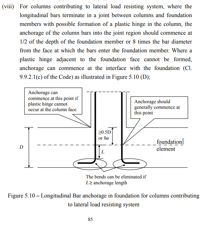
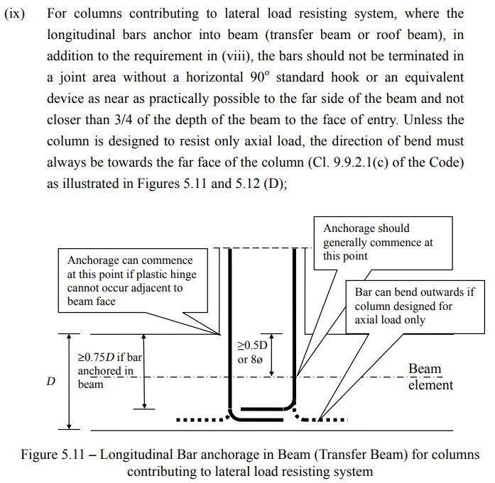
what else is required in conventional codal design other than proper detailing and developing bars for ductility? I found this useful; https://www.housingauthority.gov.hk/tc/common/pdf/business-partnerships/resources/concrete.pdf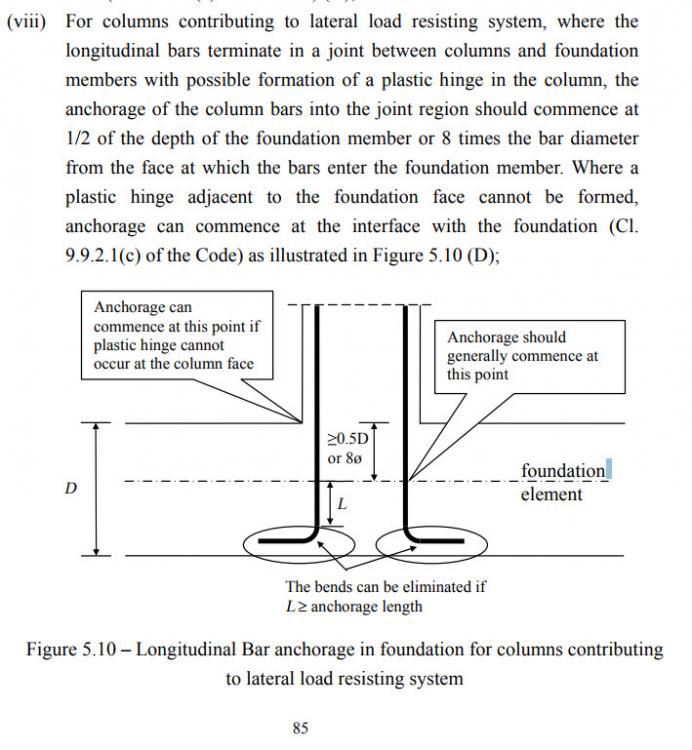
-
https://www.linkedin.com/groups/2983130/2983130-6279435049549074433
-
Look for the staad manuals for software related nomenclature. structural concepts are same and you could refer to any good book on rc/masonry design or can ask a specific question here.
-
Uplift will reverse moment diagram.
-
Yes, why not, who is stopping you?
-
ACI 318 clause for beam and column definition
WR1 replied to Samra Masood's topic in Concrete Design
Beams are flexural members only designed for the major moment and shear without axial load effects. However, column design is more accurate as you can account for biaxial bending plus axial load effect on shear. Infact all the beams can be designed by this approach. However, generally beams do not have huge axial loads or minor bending. Thats why it is simplified. -
Default Load Combination For Wind Load In Etabs 2013
WR1 replied to ahsun's topic in Software Issues
All. -
I developed this sheet long time ago. See the attached. Strap footings design.xlsx