

WR1
-
Posts
985 -
Joined
-
Last visited
-
Days Won
286
Content Type
Profiles
Forums
Events
Everything posted by WR1
-
You can as Rumman said, use semi-rigid for axial loads in slabs or there will be no force at all in the slab if you use rigid option.
-
http://www.sepakistan.com/topic/1909-modes-of-building/?hl=modes http://www.sepakistan.com/topic/1748-ritz-analysis-problem/?hl=modes#entry4694 http://www.sepakistan.com/topic/1568-few-questions-please-need-urgent-help/?hl=modes#entry3712
-
Increase the area of columns or increase stiffness of beams.
-
If you dont have a job then go for it man, look at the designation its assistant project operations. Forget about solid waste, at the end you are managing operations of a project, that project could be anything. Meanwhile, if you like the field, you can switch to a decent project management company later, if you dont you can try exploring other fields. Never say no to a new experience. If you dont know what you like at this stage (most likely), its perfectly normal. You only know after getting your hand dirty in different fields. So explore, explore and explore until you know what you gonna do next. And even other fields which you did not like, will help you to decide what you like or not.
-
I agree with Umar, why make models more complex?
-
Without looking at the model I can confirm that there is nothing wrong with the software, check your inputs, check detailed design of columns by right clicking on them. Check the unsupported lengths and see if they are correct. Also check the meshing point of slabs with columns if they are properly carrying any load. If possible upload detailed design of the column failing/giving more reinforcement here instead of model.
-
Please see SAFE manual on how to model and check soil pressure. For combinations you need to check for all service/strength load combinations as given in ACI chapter 9.
-
Please dont post ETABS files. No body got time to check in detail your model except if its a simple 2d example. Try to elaborate your question here so others can understand and can help you.
-
The answer is moment distribution. Moment distribution depends on relative stiffness of members (inertia).
-
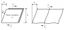
If you are doing seismic analysis, you need to make sure to take rigid beam assumption into account. Increase the beam section to 10ftx10ft, and check the shear in columns. You will find equal shear in storey columns and increasing uniformly from top to bottom corresponding to the applied lateral load. I hope that helps. Make sure you put end offsets of columns to 0 for both ends to properly see shear diagram along the full length. -------- Now comes the question of whats the difference between two. When girders are rigid, moment is computed from sway of columns x height of columns right, but in case of flexible girders, low bending stiffness of girders result in rotation at beam column joint...so additional drift and more moment. When girders are rigid (rigid-diaphragm) lateral force is distributed based on bending stiffness of vertical elements. So equal shear in all columns. When they are flexible, lateral force is distributed based on tributary area, so you see more shear in internal columns as compared to edge columns. 1/3 V in internal columns and 0.5/3 V in edge columns in this example. -------- My understanding about more shear in first storey columns is as follows. Others can correct me. In rigid-frame, shear is resisted by columns by bending in double curvature, this also bends girders in double curvature. Difference of moment of column above and below and the difference of moment of beam framing into this joint from left and right should be zero for equilibrium which is not the case and that is why columns and beams bend in double curvature. First storey columns have more shear because of shear racking. Shear racking is more significant at lower storeys and happen due to the effect mentioned above (double-curvature bending to maintain equilibrium). For example consider this example see the attached image for shear racking. Its like a couple acting as positive force at storey 2 and negative at storey 1, that in turn increases the shear in columns under storey 2 and decreases in columns under storey 1.
-
Assigning Diaphragm And Torsional Irregularity Problem
WR1 replied to Abdullah Anjum's topic in Seismic Design
Provide only 1 diaphragm with semi-rigid option to account for open area. -
There is no such thing as thermal design in ETABS. You have to use other softwares for finite element analysis for thermal stresses. For the usual design to take into account the temperature loading, don't use rigid diaphragm or it will take all the forces from T. Use usual modifiers and make a load case of T. Then you can always use minus and plus sign in combinations. Use load combinations as per ACI. T comes with 1.2 factor like dead load. Just make sure put reinforcement in beams like in columns. Equal on all faces. And the fun part, let me know how you calculate the crackwidth with P and M-M at service level. If you can't find let me know then. Good luck!
-
ETABS checks both minimum and maximum reinforcement checks for beams and columns.
-
Only for steel members
-
Keep the models simples unless you are doing a research and for which ETABS is not the best tool
-
Yes..According to Taranath, Total lateral deflection of a rigid frame is the combination of following; 1. Axial deformation of columns (15-20%) 2. Shear racking due to bending of beams (50-60%) 3. Bending of columns (15-20%) So the most economical and effective way to reduce drift is to increase beam depths (and slab thicknesses as well).
- 7 replies
-
- 3
-

-

-
- story drift
- drift
- (and 1 more)
-
In addition to that, following excerpt (attached pdf) from my dissertation might be useful. Also it is not necessary that mode 1 in ETABS is always the fundamental mode. In ETABS mode 1 will have the highest time period and so on....but also look at how much mass of the building is actually active in that mode. Building modes should be well separated; translational from torsional. What that means is T of X,Y modes should have difference from RZ mode. For example 2 seconds and 6 seconds is good difference, but 2 seconds and 2.5 seconds is of concern. Look at the comparative values of mass participation in X,Y and in RZ. For example if X has 45% mass participation, Y has 55% and RZ has 60% mass participation. These are let's say mode 1, mode 2 and mode 3 respectively. As you can see, the relative mass contribution in translational (max of X & Y is 55%) and torsional mode (60%) are quite close. This should not be a problem if Mode 1&2 and Mode 3 are well separated. Now you can look at this problem in another way (by looking at a particular mode only). For example in above example Mode was in X with 45% mass vibrating in X direction and let's say 5% in Y and remaining 50% in torsion RZ. Now it's quite difficult to determine in such case, that this is a torsional mode or a translational mode because 45% and 50% are very near. But if it was 75% in X and remaining in RZ, that would be a clear translational mode. You should include enough number of modes in ETABS so that there is atleast 90% of the building mass being involved in vibration. Otherwise increase number of modes. A rule of thumb would be No. of storeys / 10. A rigid diaphragms will have 3 degrees of freedom so 3 modes. Modes are degrees of freedom of a building. DOFs are the number of ways a building is free to vibrate. So a 5 storey structure with rigid diaphragms will have 15 active DOFs and so 15 modes, but some modes are less active and some more. Use Eigenvalue analysis, if the building is regular, stiffness and mass distribution is regular. Otherwise use RITZ which will capture the most effective modes first. A good explanation by Ashraf HabibUllah is given here for these two types of mode analysis. I hope Mr. Badr Muneeb can shed some more light on this, as this video was in AIT where he was present too. There are also other posts in this forum relating to mode shapes. For example Ritz Analysis Problem and Etabs 2013 - Story Shear, Deflections And Time Period I hope all this background will help you to understand modes shapes of building. Cheers! excerpt.pdf
-
Hinge at the top and pin at the top = pinned-pinned column. This might be the case for example in hollow core slab system. But even in that case, there is moment due to eccentricity of load. Yes you are right, building is unstable for lateral loads. BUT here in middle east which is not very active seismic region except boundaries at sea, 1.4D+1.7L combination governs instead of lateral combinations 90% of the times.
-
Let's continue it by saying that all parties are equally responsible.
-
MS Structural engineering, UET Lahore Go for it if you have interests in structures. Will open new horizons of knowledge even if later you want to switch to project management. Good to be a technical project manager. Or just keep going in structures. In short MS is highlight recommended plus I think UET is quite flexible in it's programs regarding duration (part time/evening etc). MS Construction Engineering & Management, NUST Islamabad Depends on your interests and if the location suits you. MS Disaster Management, NUST Risalpur Not much scope in Pakistan (i think), plus location is total no-no.
- 4 replies
-
- 1
-
-
- structural engineering
- Construction management
- (and 2 more)
-
How Much An Average Etabs User Can Pay For Online Training Courses
WR1 replied to WR1's topic in General Discussion
There are no training CDs etc. Try to search on youtube and other sites, there are lot of material. For drawings and models, I am afraid I cannot help you in this regard. Cannot share as these belong to the firms in which people work. I would recommend you to get a training or internship in any design office to access all the material. -
Query about progressive collapse and redundancy
WR1 replied to Mahnoor Khawaja's topic in Students Zone
A progressive collapse is a catastrophic partial or total structural failure that ensues from an event that causes local structural damage that cannot be absorbed by the inherent continuity and ductility of the structural system. If i understood your question correctly then your above statement states that progressive collapse happens due to 1. lack of redundant elements "A redundant or indeterminate structure has more structure than is absolutely necessary. " 2. lack of continuation Simply supported beam vs 3 span beam. Which one has better moment redistribution? 3. lack of ductility Shear wall system vs moment frame. Which one has better ductility. -
Without opening the model, I want to say that It could be... Redraw the area as one chunk instead of separate areas over columns Check if there is a line element over column (beam), if yes then delete it, there is no punching if beam is present
- 1 reply
-
- 2
-
-
- punching shear safe
- flat slab
- (and 1 more)
-
CSI ETABS online knowledge base or ETABS internal help files by pressing F1.
-
Following are some lines from my ms thesis; Ritz modes are more efficient specially for a tall building with higher modes and it captures the most "optimum" modes (CSI, 2011). In non-linear analysis, use of Ritz modes become essential (CSI, 2011). If the building has some flexibly elements like antena etc, use Ritz modes, it will discard the modes associated to antena. There is also a youtube video about this from Ashraf HabibUllah delivered at AIT, Thailand. Search this on youtube; Ashraf HabibUllah Eigen vs Ritz Modes Lecture
- 12 replies
-
- 2
-
-
- dynamic analysis
- response
- (and 2 more)
